
Gas burner

a burner and gas technology, applied in the field of gas burners, can solve the problems of low cost, occurrence of backfire, and relatively complicated manufacturing process, and achieve the effects of preventing the occurrence of backfire in the surrounding duct, preventing the occurrence of backfire, and low cos

Inactive Publication Date: 2007-03-15
YEN CHIA HSI
View PDF8 Cites 22 Cited by
  • Summary
  • Abstract
  • Description
  • Claims
  • Application Information

AI Technical Summary

Benefits of technology

[0006] The object of the present invention is to provide a gas burner which is manufactured at a relatively low cost and in an environmental-friendly manner, and which can prevent occurrence of a backfire therein.
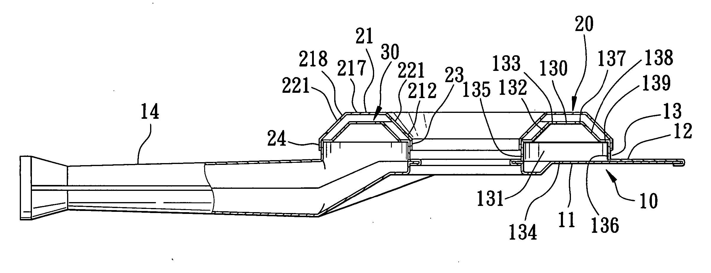
[0007] According to this invention, the gas burner includes a looped head seat and a looped burner cap. The head seat has a looped bottom wall surrounding a central axis, outer and inner surrounding walls extending respectively in an upright direction from outer and inner peripheries of the bottom wall to terminate at outer and inner edges, respectively, and a looped upper wall interconnecting the outer and inner edges. The bottom wall, the outer and inner surrounding walls, and the upper wall define a surrounding duct thereamong. The upper wall has inner and outer first surrounding regions perimetrically opposite to each other and surrounding the central axis. The burner cap has inner and outer cap peripheries that are perimetrically opposite to each other, that surround the central axis, and that are engaged with the inner and outer edges, respectively, to define a partition space between the burner cap and the upper wall. The burner cap further has an upper cap wall that extends to surround the central axis, and that is interposed between the inner and outer cap peripheries. The upper cap wall has inner and outer second surrounding regions that correspond to and that are spaced apart from the inner and outer first surrounding region, respectively, in the upright direction by the partition space. A gas conduit is disposed upstream of the surrounding duct, and is adapted for passage fuel gas to the surrounding duct. The upper wall of the head seat has a plurality of intercommunicating ports angularly displaced from one another about the central axis. The upper cap wall has a plurality of discharging orifices angularly displaced from one another about the central axis such that the fuel gas in the surrounding duct is guided to flow through the intercommunicating ports into the partition space, and is discharged through the discharging orifices. The discharging orifices are located in one of the inner and outer second surrounding regions, whereas the intercommunicating ports are located in one of the inner and outer first surrounding regions which corresponds to the other one of the inner and outer second surrounding regions. By means of the arrangement of the intercommunicating ports and the discharging orifices, occurrence of backfires in the surrounding duct can be prevented.

Problems solved by technology

The conventional gas burner is disadvantageous in that when a gas valve (not shown) is closed to stop a supply of fuel gas to the head body 1, since some fuel gas remains in the gas burner and since ambient air rapidly enters the gas burner, a backfire often occurs in the gas burner and results in a loud detonation.
Such a manufacturing process is relatively complicated and is not environmentally friendly.
However, the problem of backfiring still exists.

Method used


Image

  • Gas burner
  • Gas burner
  • Gas burner

Examples


Embodiment Construction

[0017] Before the present invention is described in greater detail, it should be noted that same reference numerals have been used to denote like elements throughout the specification.

[0018] Referring to FIGS. 3 and 4, the first preferred embodiment of a gas burner according to the present invention is shown to comprise a head unit 10 and a looped burner cap 20. The head unit 10 includes a lower shell piece 11 formed by punching a metal plate, and an upper shell piece 12 formed by punching a metal plate and secured on the lower shell piece 11 by a rolling process so as to cooperatively form a looped head seat 13 and a gas conduit 14 extending laterally and outwardly from the head seat 13.

[0019] The head seat 13 has a looped bottom wall 134 with inner and outer peripheries perimetrically opposite to each other and surrounding a central axis, an outer surrounding wall 136 extending in an upright direction from the outer periphery of the bottom wall 134 to terminate at an outer edge,...


PUM


Abstract

A gas burner includes a looped head seat formed by punching a metal plate, and defining therein a surrounding duct therein which is fluidly communicated with a gas conduit for supplying fuel gas to the surrounding duct, and a looped burner cap engaged with the head seat to define a partition space therebetween. One of inner and outer surrounding regions of an upper wall of the head seat has a plurality of intercommunicating ports, whereas one of corresponding inner and outer surrounding regions of an upper cap wall of the burner cap has a plurality of discharging orifices such that the fuel gas in the surrounding duct is guided to flow through the intercommunicating ports into the partition space and is discharged through the discharging orifices. By means of the arrangement of the ports and the orifices, occurrence of backfires in the surrounding duct can be prevented.

Description

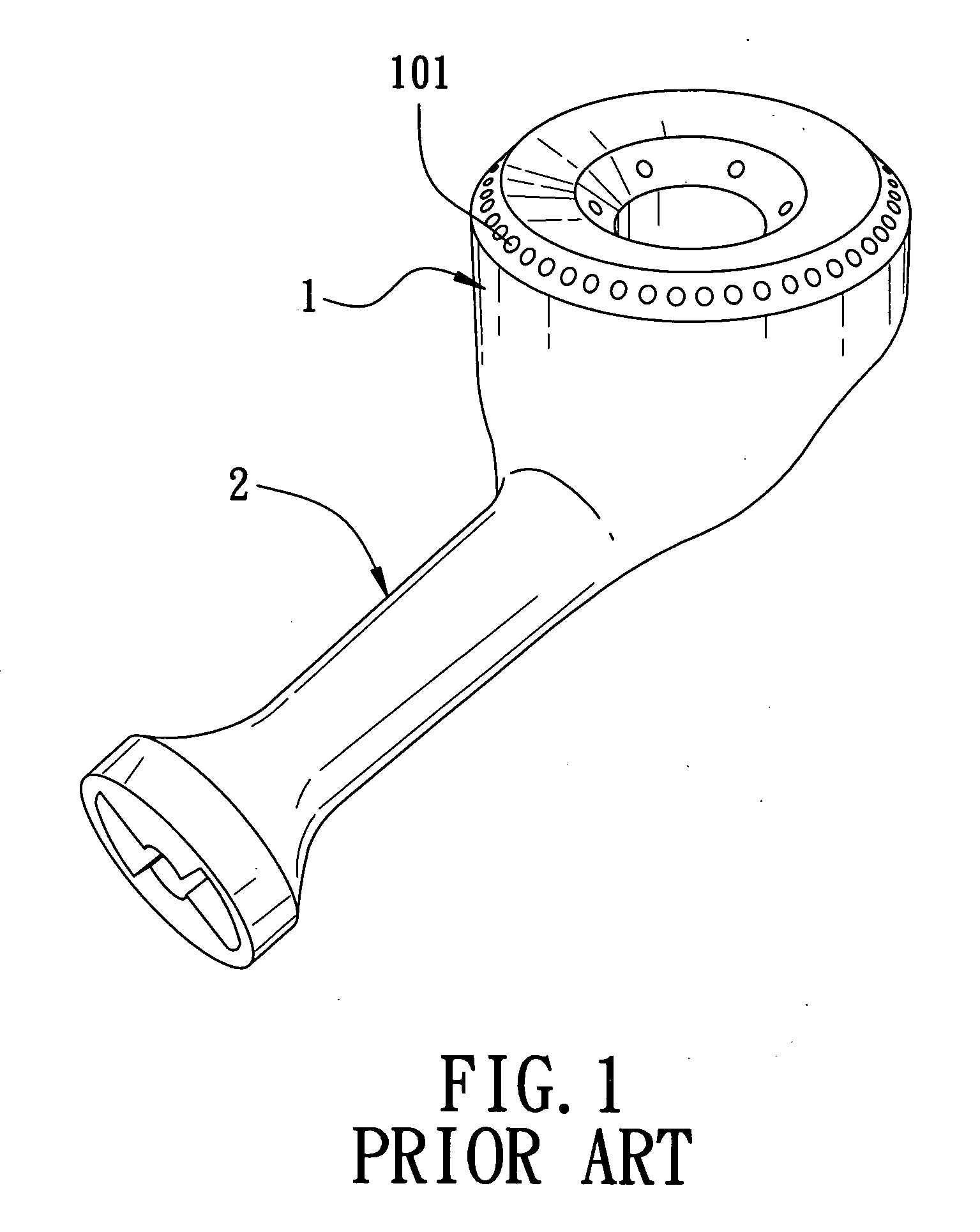
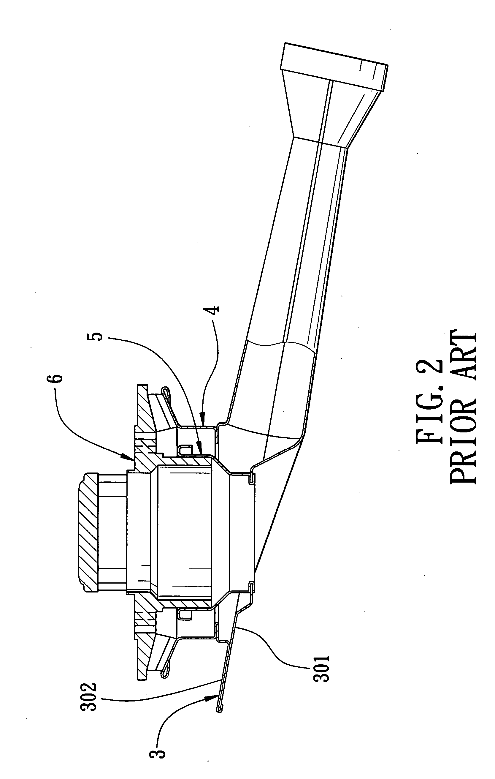
BACKGROUND OF THE INVENTION [0001] 1. Field of the Invention [0002] This invention relates to a gas burner, more particularly to a gas burner which can prevent occurrence of a backfire therein. [0003] 2. Description of the Related Art [0004] Referring to FIG. 1, a conventional gas burner is shown to include a head body 1 and a gas conduit 2 extending outwardly from and integrally formed with the head body 1 by casting. The head body 1 has a plurality of orifices 101 for ejection of flames. The conventional gas burner is disadvantageous in that when a gas valve (not shown) is closed to stop a supply of fuel gas to the head body 1, since some fuel gas remains in the gas burner and since ambient air rapidly enters the gas burner, a backfire often occurs in the gas burner and results in a loud detonation. Moreover, in manufacturing the conventional gas burner by casting, a resin material is used as a sand core, and the resin material is melted and removed when a liquid metal is poured i...

Claims


Application Information

Patent Timeline
IPC IPC(8): F23D14/62
CPCF23D14/065F23D14/58F23D2900/14062F23D2213/00F23D14/82
Inventor YEN, CHIA-HSI
Owner YEN CHIA HSI
Learn More