Coil terminal assembly for magnetic contactor

Inactive Publication Date: 2007-03-15
LS IND SYETEMS CO LTD
View PDF2 Cites 11 Cited by
  • Summary
  • Abstract
  • Description
  • Claims
  • Application Information

AI Technical Summary

Benefits of technology

[0025] Therefore, an object of the present invention is to provide a coil terminal assembly for a magnetic contactor capable of preventing a connection supporting member from being slanted in one direction when a thick external wire is inserted to or separated from the connection supporting member.

Problems solved by technology

However, in the related art coil terminal assembly for a magnetic contactor, when the external wire is a general conductive wire having a cylindrical section and having an insulation layer coated on a conductive wire, or a wire having a ‘U’-shaped terminal, a following problem is caused.

Method used


Image

  • Coil terminal assembly for magnetic contactor
  • Coil terminal assembly for magnetic contactor
  • Coil terminal assembly for magnetic contactor

Examples


Embodiment Construction

[0035] Reference will now be made in detail to the preferred embodiments of the present invention, examples of which are illustrated in the accompanying drawings.

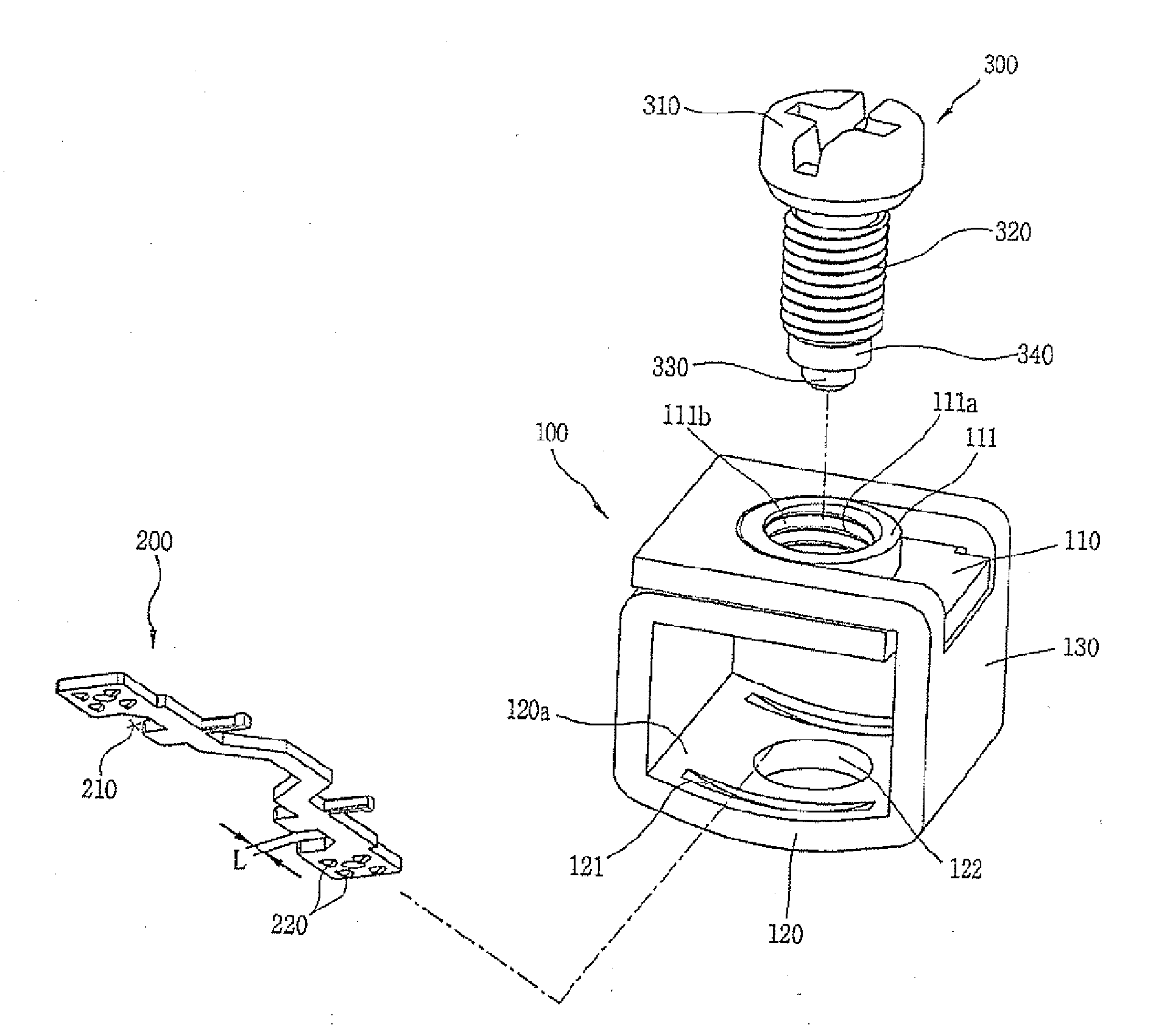
[0036] A coil terminal assembly for a magnetic contactor according to the present invention is installed at a magnetic contactor. The magnetic contactor includes a well known conductive portion (not shown) having a stationary contact (not shown) and a movable contact (not shown) movable to contact or be separated from the stationary contact, and a coil mechanism (refer to numeral 400 in the FIG. 5) for providing a driving force to drive the movable contact. And the external shape of the magnetic contactor according to the present invention can be referred to FIG. 4.

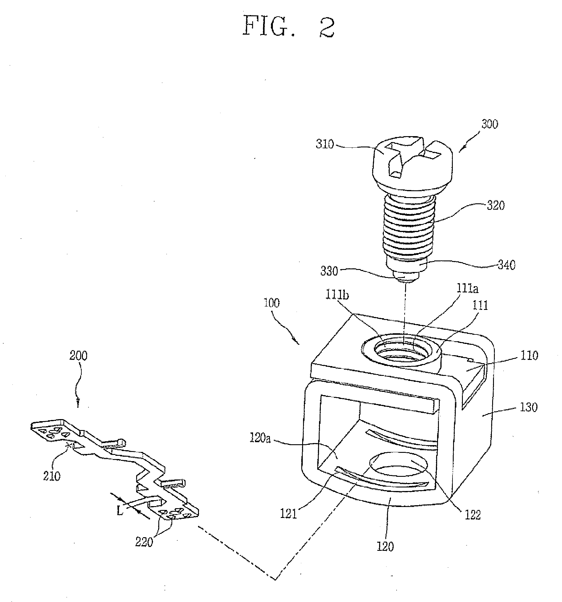
[0037] Referring to FIG. 2, the coil terminal assembly for a magnetic contactor according to the present invention comprises a coil terminal 200. The coil terminal 200 is connected to a coil 400a of the coil mechanism 400 in FIG. 5. The coil terminal 200 can be...


PUM


Abstract

A coil terminal assembly for a magnetic contactor comprises: a coil terminal connected to the coil and electrically connected to an external wire, for magnetizing the coil thereby driving the movable contact; a connection supporting member having a top portion having a threaded screw connection portion, a body portion having an opening through which the coil terminal and the external wire are inserted and providing a space in which the coil terminal and the external wire are electrically connected to each other, and a bottom portion formed as a concave surface inclined towards a center portion, the connection supporting member movable to a position for pressurizing the external wire so as to maintain an electrical connection between the external wire and the coil terminal, and movable to a position for separating the external wire from the coil terminal; and a driving screw having a threaded surface meshed with the screw connection portion, for driving the connection supporting member along the threaded surface.

Description

RELATED APPLICATION [0001] The present disclosure relates to subject matter contained in priority Korean Application No. 10-2005-0085351, filed on Sep. 13, 2005, which is herein expressly incorporated by reference in its entirety. BACKGROUND OF THE INVENTION [0002] 1. Field of the Invention [0003] The present invention relates to a coil terminal assembly for a magnetic contactor, and more particularly, to a coil terminal assembly for a magnetic contactor capable of preventing an external wire from being separated from a connection supporting member which connects a coil terminal of the magnetic contactor to the external wire, and capable of preventing a difficult driving of a driving screw which vertically moves the connection supporting member resulting from an inclination of the connection supporting member when a thick wire is used as the external wire. [0004] 2. Description of the Background Art [0005] Generally, a magnetic contactor includes a switching mechanism having a stati...

Claims


Application Information

Patent Timeline
Patent Type & Authority Applications(United States)
IPC IPC(8): H01R4/36
CPCH01H50/443H01R4/36H01H2001/5861H01H45/14H01R4/30H01R4/304H01H50/14
Inventor KIM, JUN-HO
Owner LS IND SYETEMS CO LTD
Why Eureka
Try Eureka