Control arrangement for a propulsion unit for a self-propelled floor care appliance

a floor care appliance and control arrangement technology, applied in programme control, distance measurement, instruments, etc., can solve the problems of difficult for the average user to effectively control and maneuver the vacuum, and the flexibility of providing the speed control of the propulsion drive motor is little or no, and it is difficult for the average user to exercise precise control

Inactive Publication Date: 2007-03-15
TECHTRONIC FLOOR CARE TECH LTD
View PDF19 Cites 17 Cited by
  • Summary
  • Abstract
  • Description
  • Claims
  • Application Information

AI Technical Summary

Benefits of technology

[0006] It is thus an object of the present invention to provide a self-propelled vacuum cleaner that may be controlled in accordance with movements of a handgrip maintained by the vacuum cleaner.

Problems solved by technology

However, such arrangements provide little or no flexibility in providing for controlling the speed of the propulsion drive motor.
This results in a vacuum that is difficult for the average user to effectively control and maneuver.
For example, in environments, such as a living room or bedroom, where the vacuum encounters many obstacles in its path it may be especially difficult for the user to exercise precise control so at to prevent the vacuum cleaner from colliding with such obstacles.
Moreover, the abrupt movements of the vacuum cleaner may cause physical injury to the user of the vacuum cleaner as well.

Method used


Image

  • Control arrangement for a propulsion unit for a self-propelled floor care appliance
  • Control arrangement for a propulsion unit for a self-propelled floor care appliance
  • Control arrangement for a propulsion unit for a self-propelled floor care appliance

Examples


Embodiment Construction

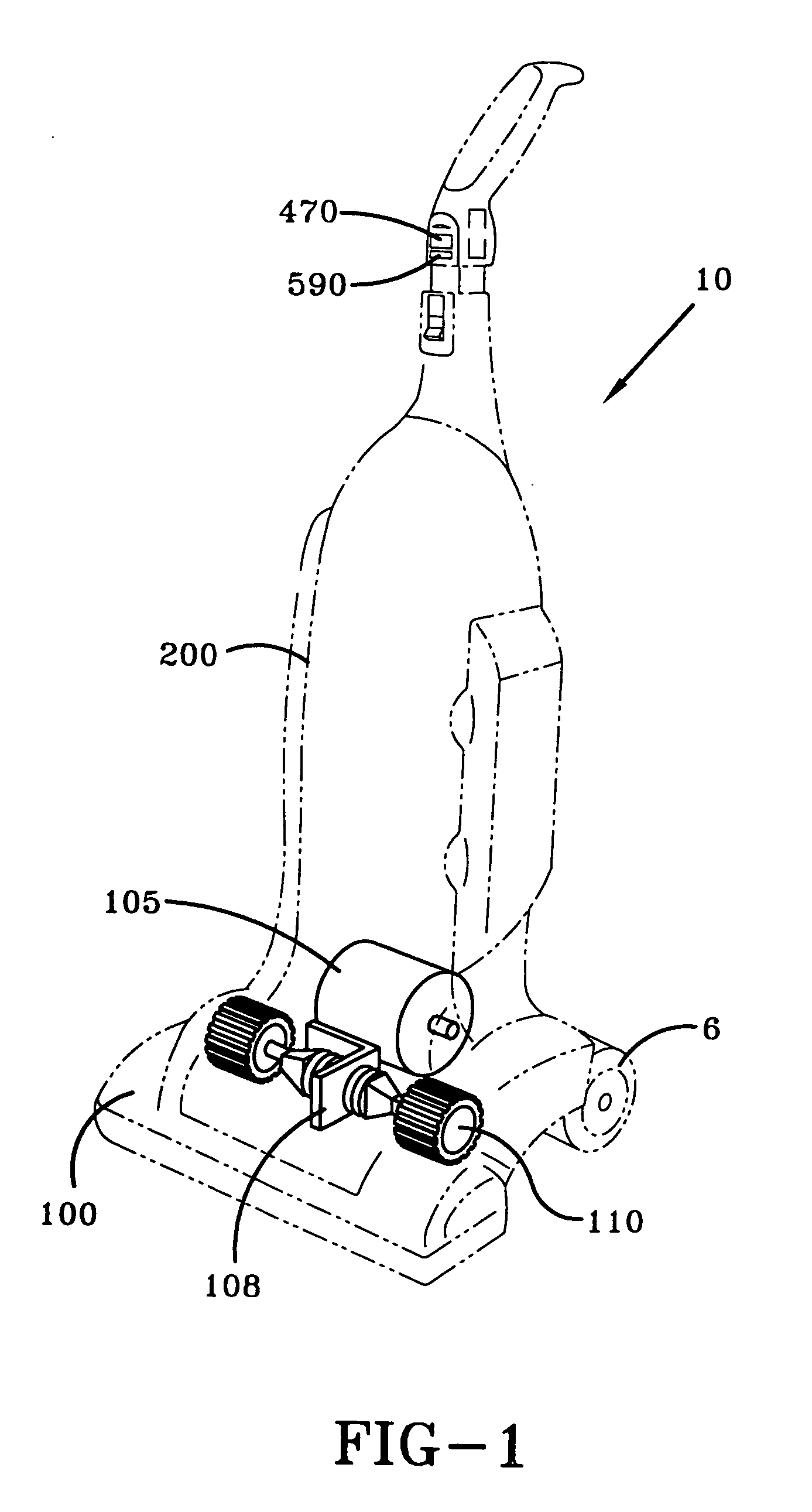
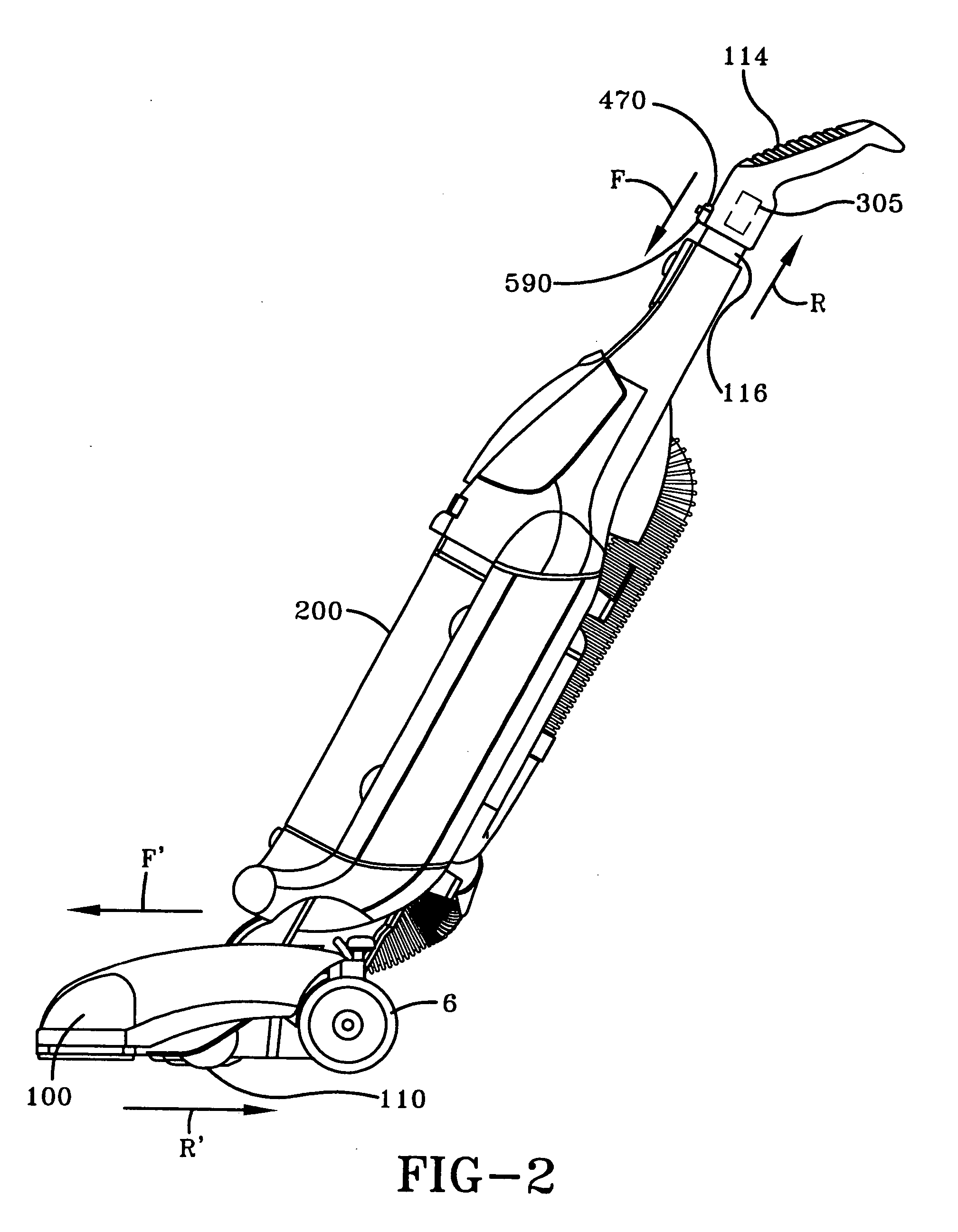
[0026] A self-propelled upright vacuum cleaner 10 is generally referred to by the numeral 10, as shown in FIG. 1 of the drawings. The vacuum cleaner 10 comprises a foot or lower engaging portion 100 that maintains an agitator (not shown) and an agitator chamber (not shown) that is formed in an agitator housing (not shown). The agitator chamber communicates with a nozzle opening (not shown), while the agitator rotates about a horizontal axis inside the agitator chamber, so as to loosen dirt from a floor surface. A suction airstream generated by a motor-fan assembly (not shown) draws the loosened dirt into a suction duct (not shown) located behind, and fluidly connected to the agitator chamber. The suction duct directs the loosened dirt to a dirt particle filtration and collecting system (not shown), which is positioned in an upper housing 200. Freely rotating support wheels 6 (only one of which is visible in FIG. 1) are located to the rear of the foot 100. The foot 100 further includ...


PUM


Abstract

A self propelled upright vacuum cleaner is provided with a Hall effect sensor to provide a Hall voltage that varies according to the position of a handgrip maintained by the vacuum cleaner. A microprocessor generates a PWM control signal to control the movement of the vacuum based on the magnitude of the Hall voltage with respect to various response characteristics, including a non-linear logistic function. As such, the vacuum cleaner imparts a user-friendly responsiveness to the user during the operation of the vacuum cleaner.

Description

CROSS-REFERENCE TO RELATED APPLICATION [0001] The instant application is a continuation-in-part of U.S. patent application Ser. No. 10 / 677,999 filed on Sep. 30, 2003, which is also incorporated herein by reference.TECHNICAL FIELD [0002] The present invention is directed to controls for a floor care appliance. Specifically, the present invention relates to a programmable control for controlling the movement of a self-propelled floor care appliance. More specifically, the present invention is directed to a programmable control that adjusts the speed of a floor care appliance in accordance with a preprogrammed response characteristic, such as a non-linear logistic function. BACKGROUND OF THE INVENTION [0003] It is known to produce a self-propelled upright vacuum cleaner by providing a transmission in the foot or lower portion of the vacuum cleaner for selectively driving at least one drive wheel in forward rotation and reverse rotation to propel the vacuum cleaner in forward and revers...

Claims


Application Information

Patent Timeline
Patent Type & Authority Applications(United States)
IPC IPC(8): G05D1/00A47L5/28A47L9/00A47L9/28A47L9/32G01C22/00
CPCA47L5/28A47L9/009A47L9/2805A47L9/2831A47L9/325A47L9/2863A47L9/2889A47L9/2894A47L9/2842
Inventor GORDON, EVAN A.MILLER, ETHAN S.
Owner TECHTRONIC FLOOR CARE TECH LTD
Why Eureka
Try Eureka