
Wearable air bag device

a technology of air bag and belt, which is applied in the direction of pedestrian/occupant safety arrangement, cycle equipment, nuclear elements, etc., can solve the problems of cumbersome electrical connection between the air bag device and the vehicle body, and achieve the effect of reducing restrictions

Inactive Publication Date: 2007-03-22
HONDA MOTOR CO LTD
View PDF12 Cites 23 Cited by
  • Summary
  • Abstract
  • Description
  • Claims
  • Application Information

AI Technical Summary

Benefits of technology

[0010] It is an object of the present invention to provide a wearable air bag device which can allow the rider to perform a connecting operation between the vehicle body and the rider easily and can reduce restrictions imparted to an operation of a rider of a motorcycle or the like.
[0015] According to the first aspect of the present invention, since the whole air bag device is incorporated into a rider's wear, an electrical connection portion or the like of the air bag device with a vehicle side becomes unnecessary thus eliminating the cumbersomeness. Further, since the necessity of an operation of the air bag device is determined based on a rotational angular speed of the reel, different from the determination based on a pulling quantity of the wire, there is no possibility that the air bag device is operated erroneously during handling the vehicle or due to a motion of a rider.
[0016] According to the second aspect of the present invention, the main switch is operated at a position closest to a rider and hence, an operability of the switch can be enhanced.
[0017] According to the third aspect of the present invention, with the provision of the common substrate, it is possible to easily incorporate the wearable air bag device into the rider's wear.
[0018] According to the fourth aspect of the present invention, for example, even when the rider forgets to release the connection between the terminal and the receiving jig and gets off the vehicle, it is possible to easily supply a detection signal to the warning device.

Problems solved by technology

However, depending on the arrangement of these parts, there exists a possibility that the electric connection between the air bag device and the vehicle body becomes cumbersome.

Method used


Image

  • Wearable air bag device
  • Wearable air bag device
  • Wearable air bag device

Examples


Embodiment Construction

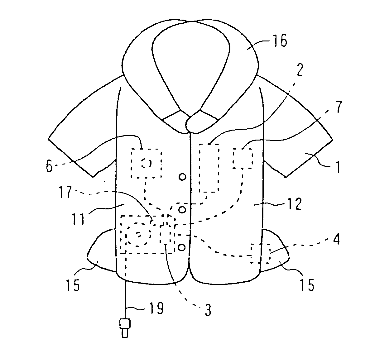
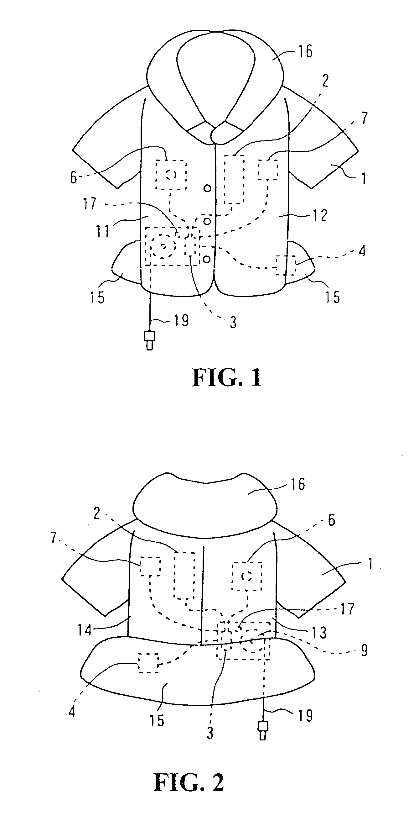
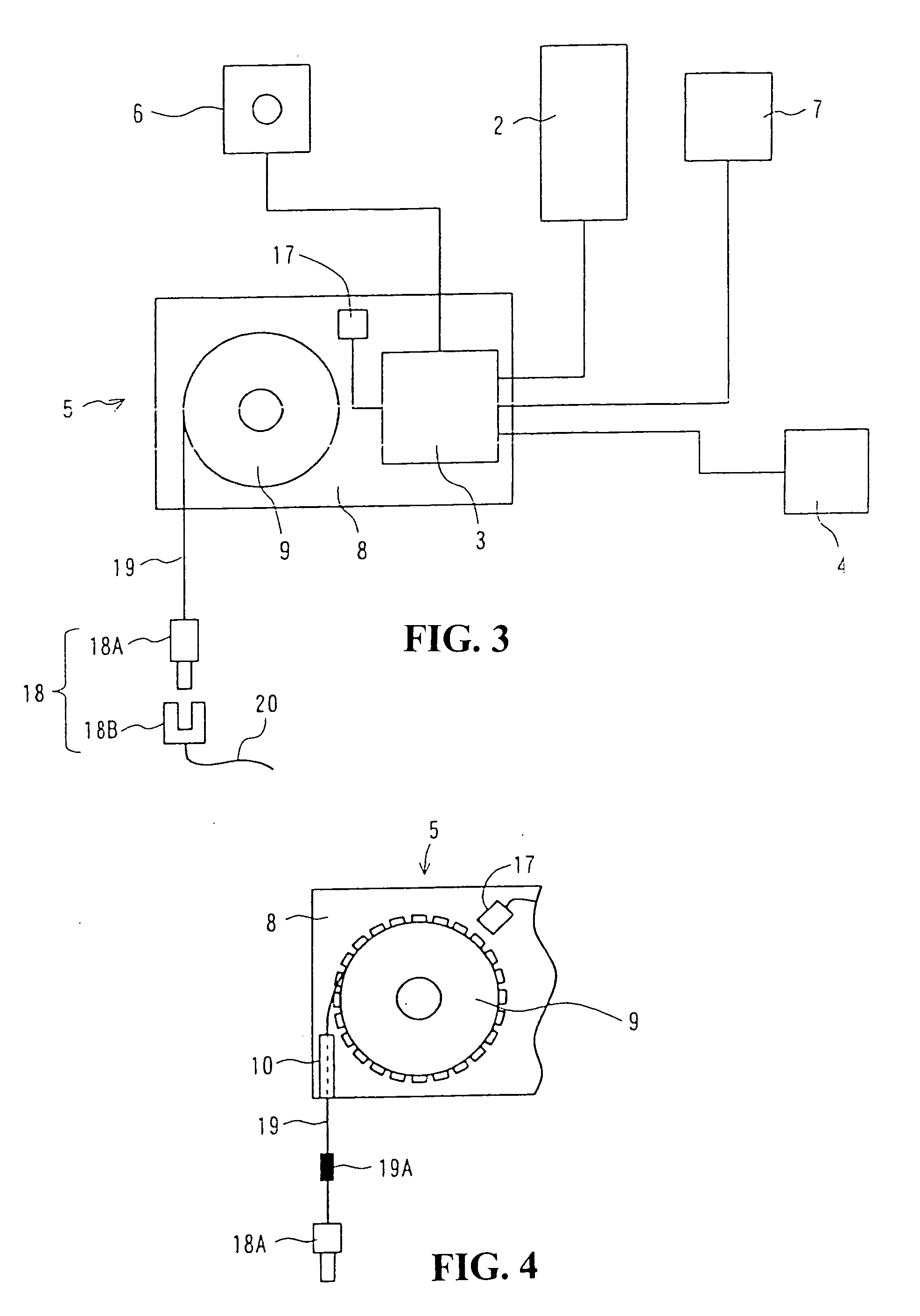
[0029]FIG. 1 is a front view of a jacket which constitutes a rider-use air bag device of a motorcycle according to one embodiment of the present invention, and FIG. 2 is a back view of the jacket, wherein both of these drawings are views in a state that the air bag is not developed. FIG. 3 is a view showing the air bag device which is separated from the jacket. FIG. 4 is an enlarged view of a rider separation detecting portion.

[0030] The jacket 1 includes an air inflating chamber which is divided into a right from portion 11, a left front portion 12, a right rear portion 13, a left rear portion 14, a waist portion 15 and a collar portion 16. These air inflating chambers are connected to an inflator 2 which supplies a gas for inflation. The inflator 2 which supplies the gas to the respective air inflating chambers when the air bag device is operated, an ECU 3 which controls the inflator 2, a battery 4 for the ECU 3, a sensor device, that is, a so-called rider separation detecting pa...


PUM


Abstract

A wearable air bag device formed by defining air inflating chambers in a jacket of a rider of a vehicle. An ECU, a battery, a rider separation detecting part, a main switch and a warning device are incorporated into the jacket. A wire is connected to a vehicle via a connecting terminal. When a rider who wears the jacket is separated from the vehicle, the wire which is connected to the vehicle is extended and a reel is rotated. Upon detecting a rotational angular speed of the reel, the ECU determines that the rider is separated when the rotational angular speed is large. Upon detection of the separation of the rider, ECU develops an air bag by operating an inflator.

Description

CROSS-REFERENCE TO RELATED APPLICATION [0001] The present application claims priority under 35 U.S.C. §119 to Japanese Patent Application No. 2005-273880, filed Sep. 21, 2005, the entire contents of which are hereby incorporated by reference. BACKGROUND OF THE INVENTION [0002] 1. Field of the Invention [0003] The present invention relates to a wearable air bag device, and more particularly to a wearable air bag device which incorporates an air bag used as a buffer device for buffering an impact to a rider of a motorcycle or the like. [0004] 2. Description of Background Art [0005] Conventionally, there has been proposed a body wear, that is, a jacket which incorporates an air inflating chamber (air bag) as a buffer for attenuating an impact to a rider of a motorcycle or the like. For example, Japanese Patent Laid-open 2002-20907 discloses a jacket provided with an air bag which is developed to cover the whole body of a rider. Further, Japanese Utility Model Registration Publication 3...

Claims


Application Information

Patent Timeline
Patent Type & Authority Applications(United States)
IPC IPC(8): A41D1/04A41D13/00B60R21/16A41D13/015B62J27/00
CPCY10S2/03A41D13/018
Inventor MAKABE, TAKUMINAGATSUYU, TOSHIYA
Owner HONDA MOTOR CO LTD
Learn More