Flow tube exercising tool

a technology of flow tube and exercise tube, which is applied in the direction of fluid removal, borehole/well accessories, construction, etc., can solve the problems of inoperable safety valve, difficult to physically move upward and downward, and scale, dirt and other debris in the production tub

Inactive Publication Date: 2007-03-22
BAKER HUGHES INC
View PDF5 Cites 11 Cited by
  • Summary
  • Abstract
  • Description
  • Claims
  • Application Information

AI Technical Summary

Benefits of technology

[0014] The flow tube exercising tool of the present invention provides a number of advantages over conventional systems. The flow tube of the safety valve may be exercised (i.e., moved axially with respect to the safety valve housing) without the risk of damage from the setting of slips. Only a single trip of the flow tube exercising tool is necessary to accomplish multiple upward and downward movements of the flow tube. Additionally, the flow tube is exercised without the need to operate the hydraulic actuator of the safety valve.

Problems solved by technology

One problem that has traditionally been faced by valves of this type is that scale, dirt, and other debris will often build up within the production tubing during typical production operations.
This build up can render the safety valve partially or completely inoperable.
The most deleterious build up will be that which occurs on and around the flow tube that is used to open the valve, making the flow tube difficult to physically move upwardly and downwardly.
This means that the valve will be unable to function well in the event of an emergency requiring production flow to be closed off.
The use of explosives, however, carries with it risks of damage to wellbore valve components as well as the potential for a breach of the production tubing string.
Unfortunately, tools of this type tend to physically damage the flow tube and other wellbore components, due to the use of the slips.
However, there may be instances wherein this type of flow tube exerciser is not practical.

Method used


Image

  • Flow tube exercising tool
  • Flow tube exercising tool
  • Flow tube exercising tool

Examples


Embodiment Construction

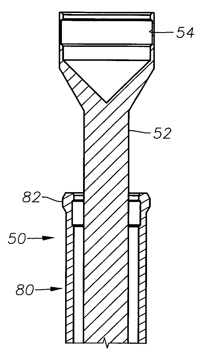
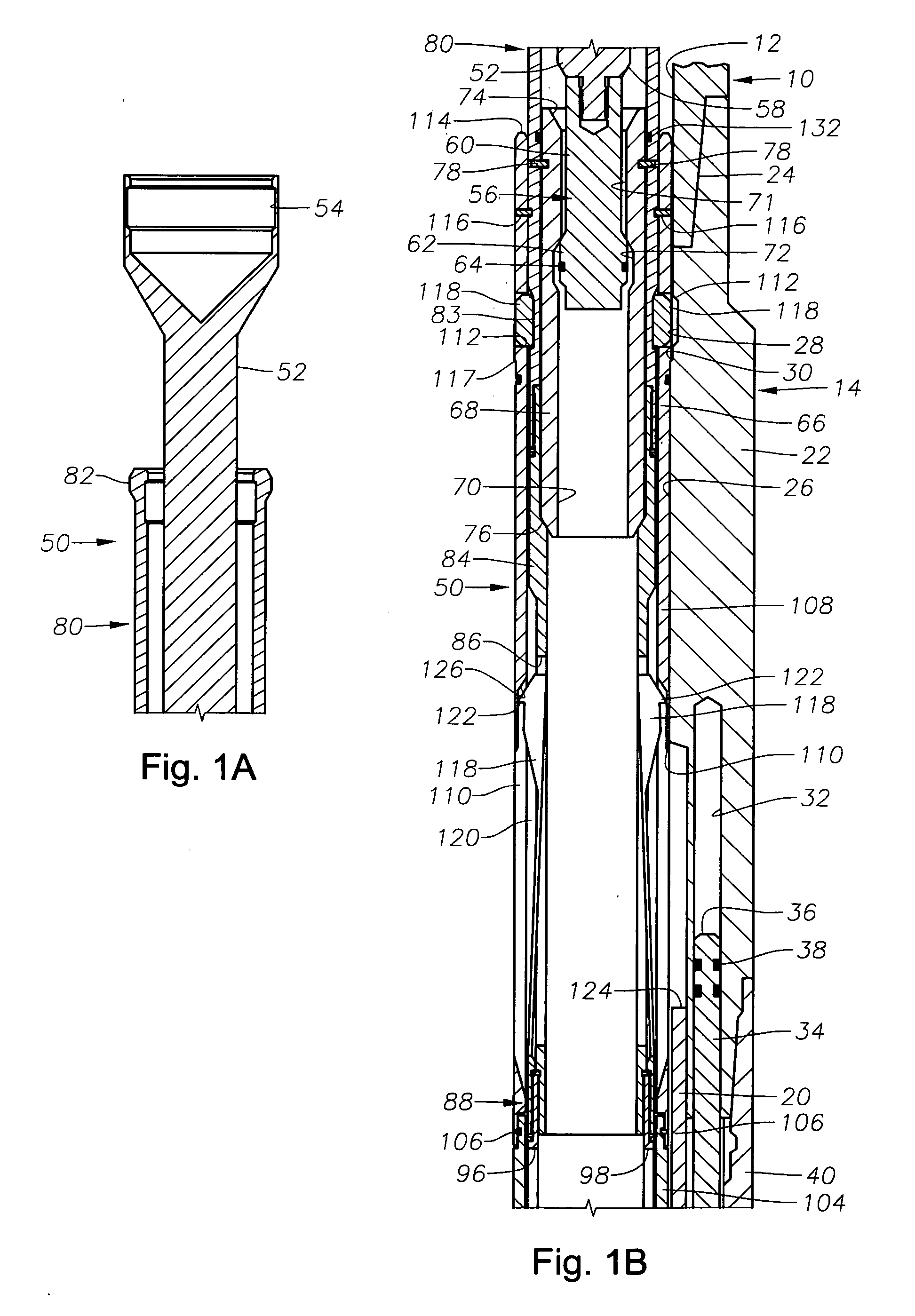
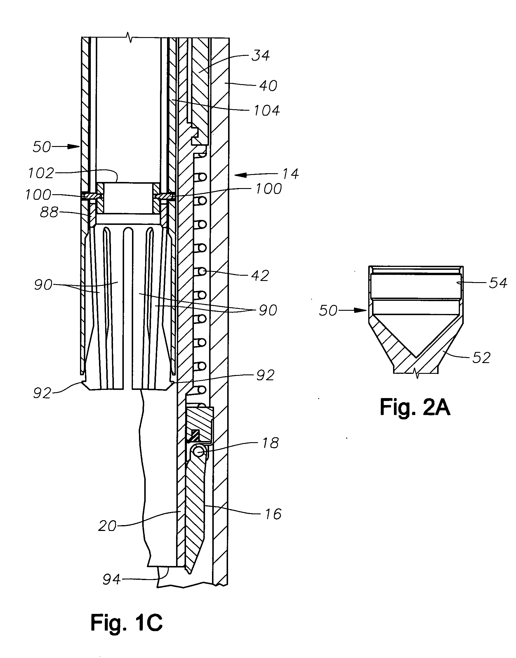
[0020]FIGS. 1A, 1B and 1C illustrate a section of portion of a string of production tubing 10, of a type known in the art that defines a production flowbore 12 along its length. A safety valve, generally indicated at 14 is integrated into the production tubing string 10. The safety valve 14 is a flapper valve, of a type that is well known in the art and described in, for example, U.S. Pat. No. 4,415,036 issued to Carmody. U.S. Pat. No. 4,415,036 is owned by the assignee of the present invention and is incorporated herein by reference. In the safety valve 14, a flapper valve member 16 rotates in a pivoting manner about a hinge 18 and is biased toward a closed position by a spring (not shown), in a manner well known in the art. The flapper member 16 is opened and retained in an open position (as illustrated in FIG. 1C) by an axially moveable flow tube 20 which, in turn, is actuated by a hydraulic piston-type controller (not shown) of a type known in the art.

[0021] At its upper end, t...


PUM


Abstract

A flow tube exercising tool and method for use are described for actuating the flow tube of a downhole safety valve in order to remove build ups of scale and debris from the safety valve and ensure proper operation. The exercising tool provides a lower engagement portion that underlies the lower end of the safety valve flow tube so that upward movement of portions of the exercising tool will move the flow tube upwardly. An upper engagement portion overlies the upper end of the flow tube so that downward movement of portions of the exercising tool will move the flow tube downwardly. Only a single trip of the flow tube exercising tool is necessary to accomplish multiple upward and downward movements of the flow tube.

Description

[0001] This application is a continuation-in-part to U.S. patent application Ser. No. 11 / 131,726 filed May 18, 2005.BACKGROUND OF THE INVENTION [0002] 1. Field of the Invention [0003] The invention relates generally to methods and devices for cleaning and remediating a subsurface safety valve or other downhole tool having a sliding flow tube member. [0004] 2. Description of the Related Art [0005] Flapper-type valves are often used as safety valves within wells to selectively close off production. The usual flapper valve uses a torsion spring to bias the valve member toward a closed position. During normal operation, however, the flapper member is retained in an open position by an axially moveable flow tube. When the flow tube is moved upwardly within the production tubing, the flapper member is permitted to close under influence of the spring. To reopen the valve, the flow tube is moved downwardly within the production tubing to urge the valve back towards its open position. [0006]...

Claims


Application Information

Patent Timeline
Patent Type & Authority Applications(United States)
IPC IPC(8): E21B29/02E21B37/00E21B43/00
CPCE21B23/04E21B2034/007E21B37/00E21B2200/06E21B34/14
Inventor LAYTON, BENNY C.
Owner BAKER HUGHES INC
Why Eureka
Try Eureka