Backlight module and a light-emitting-diode package structure therefor

a backlight module and package structure technology, applied in the field of light emitting devices, can solve the problems of considerable limitation of the application of the conventional backlight module, achieve the effect of reducing the size of the backlight module, widening the application range, and uniform light mixing

Active Publication Date: 2007-03-22
NYTELL SOFTWARE LLC
View PDF8 Cites 51 Cited by
  • Summary
  • Abstract
  • Description
  • Claims
  • Application Information

AI Technical Summary

Benefits of technology

[0013] In addition, the present invention is further directed to a backlight module implementing the aforementioned LED package structure as a light source to provide a light of uniform chroma and brightness. Moreover, this backlight module is suitable for a lighter and thinner panel display due to its lower-volume and lighter-weight in comparison with the conventional backlight module.
[0024] The LED package structure of the present invention can provide light-converging and light-scattering functions in all axes, and in comparison with the conventional single LED package structure's light-converging or light-scattering functions, the LED package structure of the present invention can have a wider application. Especially in the field of backlight module, the LED package structure of the present invention applied as a light-emitting element could not only provide more uniform light-mixing in a shorter distance but also reduce the backlight module size, thus promoting light utilization of the backlight module.

Problems solved by technology

As a result, in today's trend of minimized display products, such a conventional backlight module is considerably limited in its applications.

Method used


Image

  • Backlight module and a light-emitting-diode package structure therefor
  • Backlight module and a light-emitting-diode package structure therefor
  • Backlight module and a light-emitting-diode package structure therefor

Examples


Embodiment Construction

[0033] Reference will now be made in detail to the present embodiments of the invention, examples of which are illustrated in the accompanying drawings. Wherever possible, the same reference numbers are used in the drawings and the descriptions to refer to the same parts.

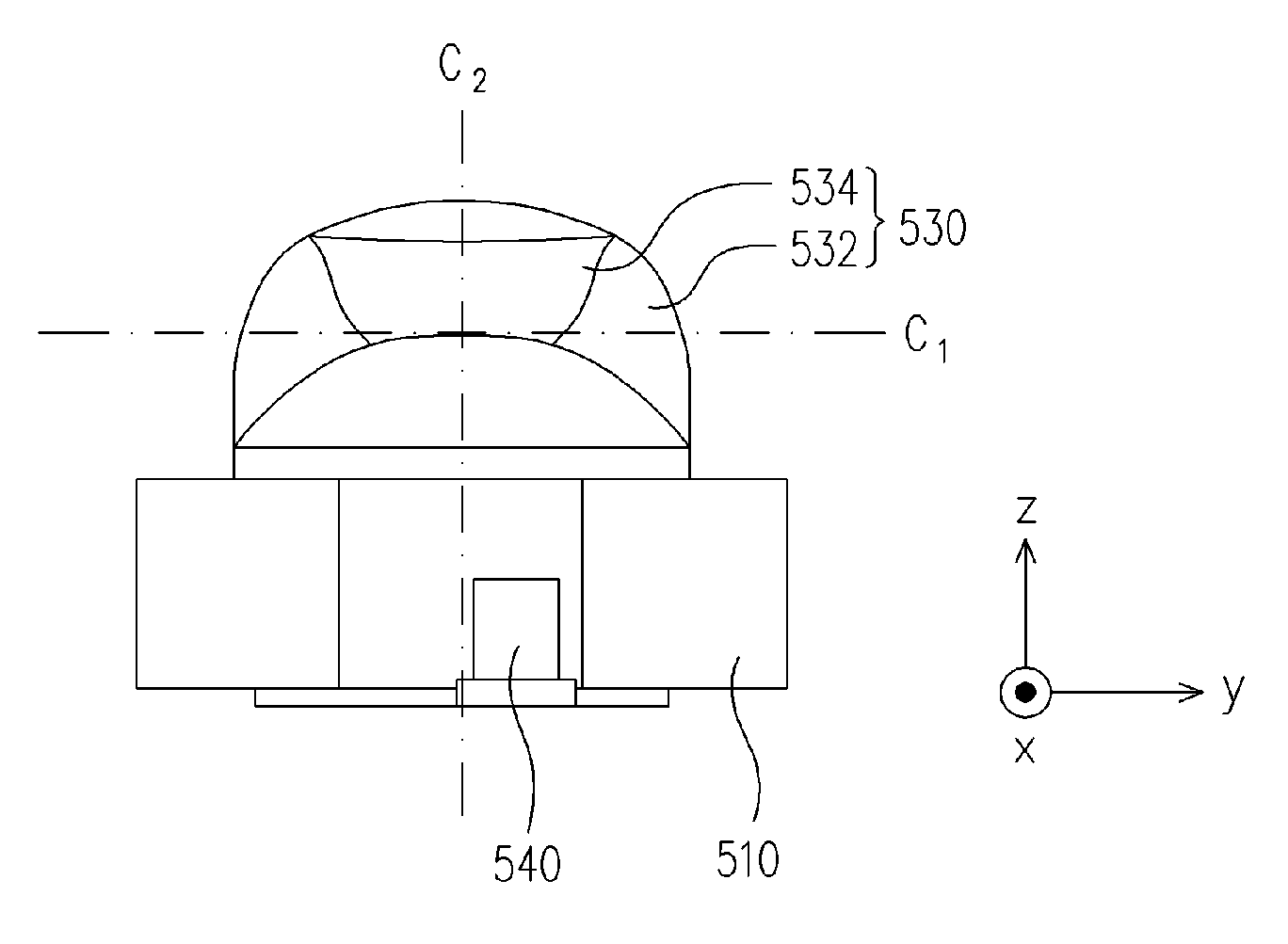
[0034]FIG. 5A shows a three-dimensional view of an LED package structure of the present invention. Whereas, FIGS. 5B and 5C respectively shows side views of the LED package structure in FIG. 5A from different axes. As shown in FIG. 5A, an LED package structure 500 comprises a substrate 510, an LED chip 520, a plastic package body 530, a first leading leg 540, and a second leading leg 542. In addition, the LED chip 520 is arranged on the substrate 510 and may comprise a red light LED chip, a green light LED chip or a blue light LED chip.

[0035] Furthermore, the plastic package body 530 is also disposed on the substrate 510 and covers the LED chip 520. Especially, the plastic package body 530 comprises a light-conver...


PUM


Abstract

The LED package structure includes a substrate, an LED chip, a plastic package body, and two leading legs. In addition, the LED chip is arranged on the substrate and covered by the packaging plastic body. Moreover, the plastic package body contains a light-converging part and a light-scattering part, in which the light-converging part has a first axis and the light-scattering part has a second axis. In addition, the first axis of the light-converging part intersects the second axis of the light-scattering part. Furthermore, one terminal of each of the two leading legs is electrically connected to the LED chip while another terminal extends out of the packaging plastic body. Because the LED package structure can converge light and scatter light in different directions, the backlight module implementing the LED package structure has the advantage of a shorter light-mixing distance and better light utilization.

Description

BACKGROUND OF THE INVENTION [0001] 1. Field of the Invention [0002] The present invention generally relates to a light-emitting device, and more particularly, to a backlight module and a light-emitting-diode (LED) package structure therefore. [0003] 2. Description of Related Art [0004] A backlight module is usually classified into a side type and a direct type, wherein the side type requires a light- guiding plate to convert a linear light source into a planar light source required by a liquid crystal display (LCD) panel. In addition, because the LEDs have the advantages of higher color saturation, mercury-free material, higher lifespan, a lower operating temperature, and a variable color adjustment by a driven current, an LED array has gradually been implemented in the backlight module. [0005]FIGS. 1A, 2A, and 3A respectively shows cross-sectional views of conventional Lambertian, Batwing, and side-type LED package structures. Moreover, FIGS. 1B, 2B and 3B respectively shows the re...

Claims


Application Information

Patent Timeline
Patent Type & Authority Applications(United States)
IPC IPC(8): H01L33/00H01L33/58
CPCG02B6/0025G02B6/003H01L33/58G02B6/0055G02B6/0036
Inventor CHIU, TIEN-LUNGTSENG, WEI-YANG
Owner NYTELL SOFTWARE LLC
Why Eureka
Try Eureka