Interface system for retaining a foot or a boot on a sports article

a technology for sports articles and sports shoes, applied in snowboard bindings, sports equipment, transportation and packaging, etc., can solve the problems of not being able to dynamically conform to the background art, not being able to secure the user's heel to the snowshoe, and never being able to offer the comfort and performance of strap bindings, etc., to achieve the effect of increasing comfort and performance, less tension, and more surface area

Inactive Publication Date: 2007-03-22
KAVARSKY RAYMOND R
View PDF16 Cites 76 Cited by
  • Summary
  • Abstract
  • Description
  • Claims
  • Application Information

AI Technical Summary

Benefits of technology

[0032] The purpose of the preferred embodiments of the invention is to provide a no-compromise, high-performance snowboard-rider interface system, utilizing innovative design and quality construction Preferred embodiments of the invention provide a level of comfort and performance unprecedented in the snowboard industry. The benefits obtained allow snowboarders to ride longer, more comfortable days. The system provides a more natural and responsive interface with the board, thereby enhancing the riding experience and providing the ability for more technical and advanced maneuvers.
[0033] Enhancements in comfort and performance derive primarily from the preferred lace wrap retention system, which replaces conventional toe and ankle straps with single- or multi-piece lateral and medial linkage members providing more surface contact area than traditional toe and ankle straps. A heel segment is also incorporated into other preferred embodiments. The configuration of the linkage members provides a dynamic “web” of retention that is able to conform to the complex shape of the human foot better than any other strap binding technology. Using only very thin or non-existent padding layers, the lace wrap retention system inherits elements of its performance traits from the traditional and proven method of a crisscross shoelace system.
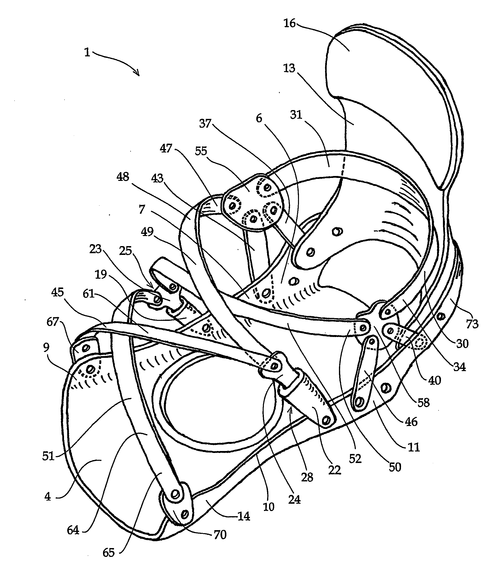
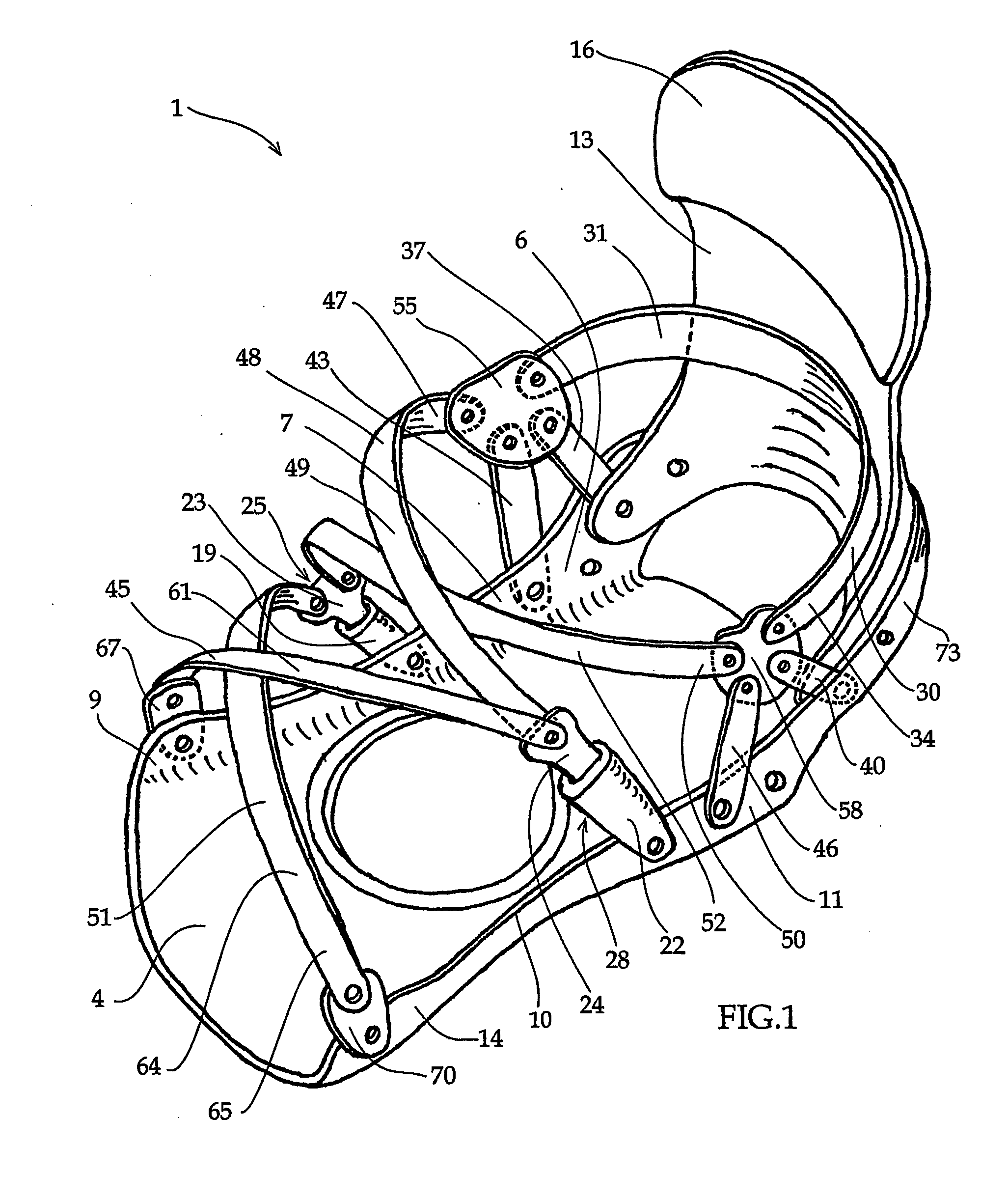
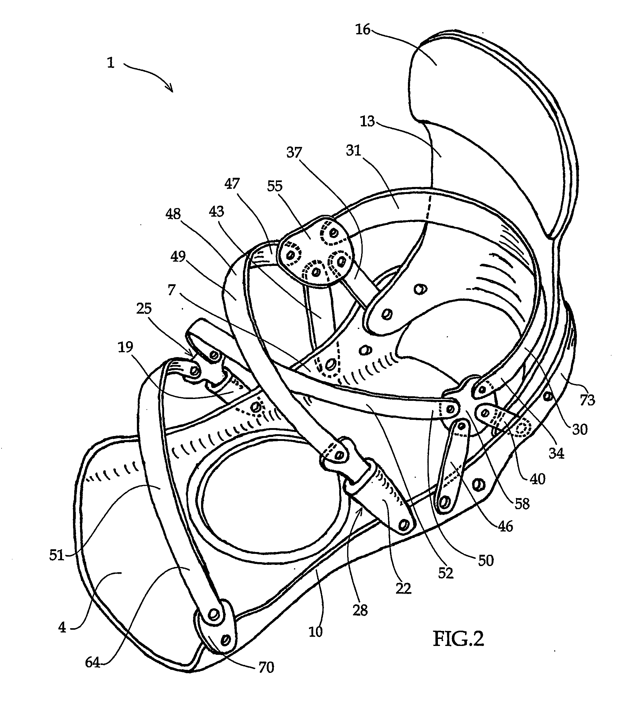
[0035] The lace wrap retention system is intended to replace conventional toe and ankle straps with a single- or multi-piece wrap device, providing more surface area than conventional straps. Therefore, the system requires less tension to achieve the same level of security and control, resulting in increased comfort and performance for the rider. Certain embodiments of the lace wrap also provide resistance against the problem of heel lift by incorporating a linkage, which provides retention to the back side of the rider's heel. Because the lace wrap is preferably constructed of a thin pliable material and is configured in a crisscross manner (similar to a shoe lace), it is far more able to conform locally to the shape of the user's foot than a conventional two-strap system. Providing a dynamic web of retention that is responsive in all directions, this last trait provides a more genuine “interface” between the board and rider.
[0036] Preferred embodiments of the present invention also offer the user the ability to adjust the lateral / medial flex of the heel loop and / or vertical support member (high back) by the means disclosed herein. This eliminates the need to manufacture multiple product models and offers custom tailored performance to a multitude of riding styles and conditions, in one product model. This is accomplished by positioning a bumper component on either side of the heel loop portion of the base structure or the vertical support member. This bumper component is positioned so as to interfere with, and thus limit the flex of the heel loop or vertical support member when either of those components is flexed in the lateral or medial direction during various snowboarding maneuvers. Preferably, the bumper component is adjustably mounted on a rigid support member. The support member may be mounted on the base structure or alternatively, be part of the base structure. This rigid support member is preferably located in the general area of the side of the heel loop portion of the base structure approximately following the profile of the heel loop surface and being substantially widened away from the base structure. The support member has an inside surface which is angled away from the heel loop portion so as to allow unrestricted flex of the heel loop and vertical support member.
[0037] Preferably, the bumper component is mounted so as to protrude past this surface, towards the outer surface of the heel loop or vertical support member, at a distance which is adjustable, and, therefore, allows different limits on the flex of the heel loop and / or vertical support member. It is further preferred that the bumper component be mounted in a slot of the rigid support member so that it may be positioned to interfere with different locations on the outside surface of the heel loop portion of the base structure or the vertical support member. This allows even greater customization of the flex patterns and limits of motion of the heel loop and / or vertical support member.
[0039] Another aspect of preferred embodiments of the invention is the addition of a tool used for adjusting the various fasteners of the system. This tool is preferably mounted on the outside surface of the vertical support member and may be incorporated into other binding systems as well. The addition of a multi tool mounted to the vertical support member is of benefit to the user needing on-the-spot adjustment It also eliminates the need for a user to carry a tool on his / her person while performing a sports activity, which can be dangerous.

Problems solved by technology

Although the step-in binding has been very popular (mainly with the rental and beginner market), it has never been able to offer the comfort and performance of a strap binding.
Moreover, no means are provided to secure the user's heel to the snowshoe to allow the user's toe to dip downward into the snow.
The problem with increasing the thickness of the padding is that it results in more movement of the foot within the constraints of the binding (because of the compression of the padding) this also results in more, undesirable, heel lift The technique of providing a more anatomically-shaped system along with more surface area does, however, increase comfort levels, and is a common practice in any art dealing in an interface with the human body.
One company, Flow, has taken the increase in surface area technique to the extreme of having one single mostly homogenous strap (or pad) that covers most of the front / top of the user's foot While this system does reduce the required tension of the strap, it is not locally conformable due to the complex shape of the foot The main focus of the Flow system is entry / exit convenience by means of a rear-entry type system.
The background art is also lacking a dynamically conformable retention system capable of being adapted (or adjusted) to the user's specific ankle axis geometry.
The applicant believes that this connection method does not provide adequate tension of the heel strap in the proper direction, nor does it provide sufficient resistance to the keep the boot pulled back towards the vertical support member and therefore, is not as effective as the configuration of the present invention.
This is presently accomplished by altering the geometry and thickness of the components or by the use of different rigidity of material in the base, heel loop, and vertical support members, e.g., using a thirty percent glass filled polymer instead of twenty percent glass filled polymer to achieve a less flexible component This method however does not offer the user any means of adapting the system to their preferred levels of flex.

Method used


Image

  • Interface system for retaining a foot or a boot on a sports article
  • Interface system for retaining a foot or a boot on a sports article
  • Interface system for retaining a foot or a boot on a sports article

Examples


Embodiment Construction

[0183] It is noted that only a right-footed embodiment is disclosed herein with the understanding that a similar device would be provided for the left foot, being anatomically symmetric to the right-footed device, or being a copy of the same device.

[0184] Referring to FIG. 1, a preferred embodiment of interface system 1 is presented. In this embodiment, interface system 1 preferably comprises rigid base structure 4, vertical support member 13, and three pliable linkage members: lateral linkage member 48, medial linkage member 51 and heel linkage member 30.

[0185] Base structure 4 preferably comprises (1) lateral edge 7 having lateral back portion 6 and lateral front portion 9, (2) medial edge 10 having medial back portion 11 and medial front portion 14, and (3) heel loop portion 73. Preferably, heel loop portion 73 is adjustably connected to rigid base structure 4 by conventional means, e.g., bolts or rivets. Alternatively, rigid base structure 4 and heel loop portion 73 are molded...


PUM


Abstract

An interface system (1) comprising one or more linkage member(s) (30, 48, 49, 51, 52, 61) that have the purpose of retaining an individual's foot / ankle (either bare or covered) on a sports article. The system (1) comprises a rigid base structure (4) a having lateral edge (7) and medial edge (10), and heel loop portion (73); one or more pliable linkage members (30, 48, 49, 51, 52, 61) that wrap around the user's foot / ankle or boot and are tensionably adjustable and disconnectable.

Description

CROSS-REFERENCE TO RELATED APPLICATIONS [0001] This application claims the benefit of U.S. Provisional Application No. 60 / 382929, filed May 21, 2002, the disclosure of which application is incorporated by reference as if fully set forth herein.STATEMENT REGARDING FEDERALLY SPONSORED RESEARCH OR DEVELOPMENT [0002] Not Applicable TECHNICAL FIELD [0003] This invention relates to an interface system for retaining a foot or a boot on a sports article. In particular, the invention relates to an interface system for retaining a human foot / ankle (either bare or covered) on a snowboard, snowshoe, wakeboard, inline skate or other sports article. The system may also be used as an internal or external support structure for a boot or other footwear. Although the field of application of the invention is broad, its preferred application is as a snowboard interface system. Consequently, this disclosure addresses that application. BACKGROUND ART [0004] Current snowboard binding designs consist mainl...

Claims


Application Information

Patent Timeline
Patent Type & Authority Applications(United States)
IPC IPC(8): B62B13/00A63C10/04A63C10/06A63C10/22A63C10/24A63C10/28
CPCA63C10/04A63C10/06A63C10/285A63C10/24A63C10/22
Inventor KAVARSKY, RAYMOND R.
Owner KAVARSKY RAYMOND R
Why Eureka
Try Eureka