Adjustable LED luminaire

a led luminaire and led light technology, applied in the field of luminaires, can solve the problems of significantly changing the appearance of lighted areas and being able to be varied, and achieve the effect of eliminating high-voltage ballasts

Inactive Publication Date: 2007-03-22
AWI LICENSING
View PDF18 Cites 174 Cited by
  • Summary
  • Abstract
  • Description
  • Claims
  • Application Information

AI Technical Summary

Benefits of technology

[0016] One advantage of the present invention is the ability to vary the ratio of direct to indirect light emitted by a luminaire.
[0017] Another advantage is the ability to change the ratio of direct to indirect light emitted by a luminaire by rotating the light source, without the need to modify the geometry of the luminaire.
[0018] Another advantage is the ability to provide a luminaire with standard or non-standard ratio of direct to indirect light distribution.
[0019] A further advantage of the present invention is the elimination of high voltage ballasts.
[0020] Yet another advantage of the present invention is the ability to remotely control the ration of direct to indirect light emitted from luminaries after installation of the fixture in a ceiling or grid pattern.
[0021] Other features and advantages of the present invention will be apparent from the following more detailed description of the preferred embodiment, taken in conjunction with the accompanying drawings which illustrate, by way of example, the principles of the invention.

Problems solved by technology

Once the light distribution profile of a luminaire is set in the manufacturing stage it is not capable of being varied without disassembling and rebuilding the entire fixture with different components.
The directional nature of the diodes themselves creates a situation where a slight angular change in the installation can significantly change the appearance of lighted areas.

Method used


Image

  • Adjustable LED luminaire
  • Adjustable LED luminaire
  • Adjustable LED luminaire

Examples


Embodiment Construction

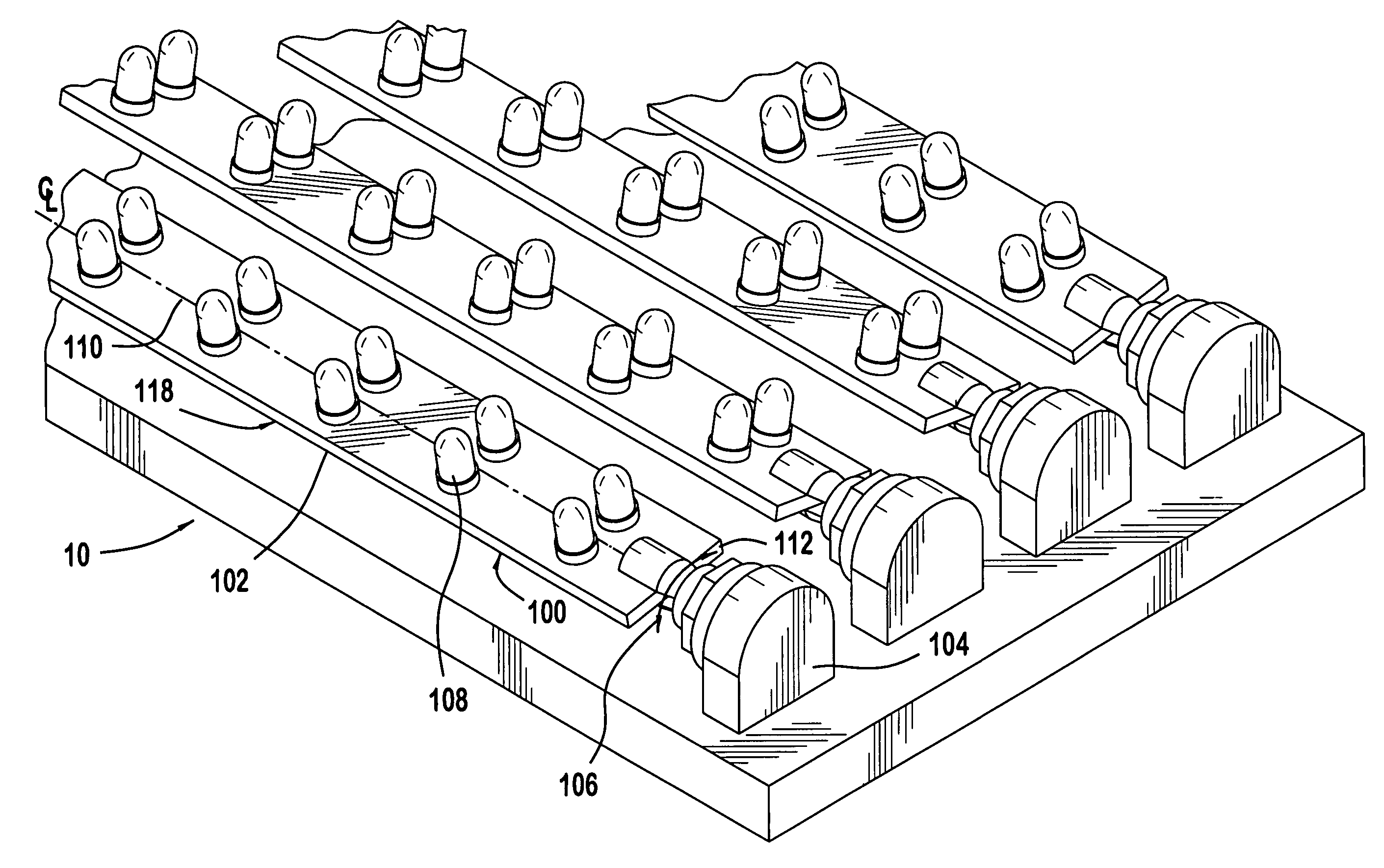
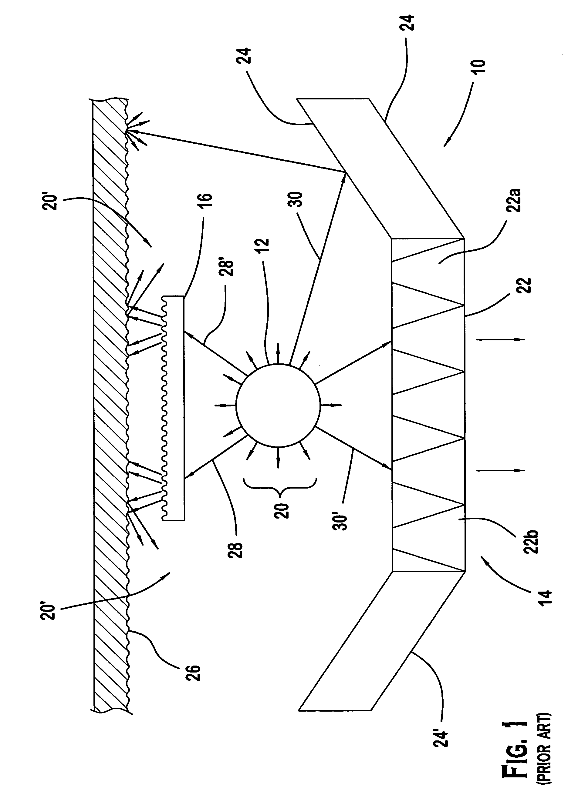
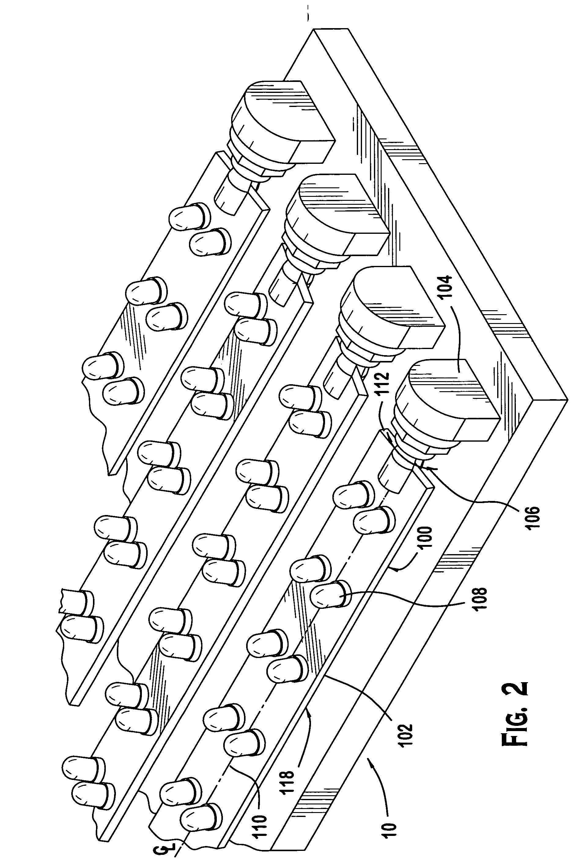
[0026] Referring to FIGS. 2, 3&3A, a luminaire is generally designated as 10. A plurality of LED assemblies 100 are disposed between a louver portion 14 and a diffuser lens 16. Rays of light 20 are emitted radially from LED's 108 in a predetermined cone arrangement. FIGS. 3 and 3A are similar to FIG. 1, except that the tubular source, such as a prior art fluorescent tube emitting light uniformly in all directions is replaced by LED assemblies, which are somewhat directional. Louver portion 14 includes a baffle portion 22 and reflector plates 24, 24′ arranged at opposite sides of the baffle portion 22, preferably angled upward toward the ceiling to partially shroud the light source 12 from direct view. Baffle portion 22 typically includes a plurality of baffle segments 22a and openings 22b. Baffle segments 22a are arranged in a grid or in parallel relation with each other, for reflecting and redirecting the impinging light rays 20. Openings 22b are defined by the baffle segments 22a ...


PUM


Abstract

A lighting fixture apparatus includes a frame portion, a louver portion and a diffuser lens. The louver portion includes a baffle system for passing unobstructed at least a portion of the light impinging thereon. The diffuser lens includes a surface for diffusing light rays. At least one directional lighting apparatus comprised of LED strips is attached to and supported by the frame portion. The LED strips are disposed between the louver portion and the diffuser portion. The LED assembly includes a rigid strip having a first end and a second end opposite the first end portion, and a first surface and a second surface opposite the second surface. A first rotary support member and a second rotary support member are connected to the strip portion at respective first and second ends. A plurality of electrical lighting elements are mounted on the first surface and are configured in at least one electrical circuit.

Description

FIELD OF THE INVENTION [0001] The present invention is directed to a luminaire, and more particularly to a luminaire having a light source comprising light-emitting diodes (LEDs). BACKGROUND OF THE INVENTION [0002] Conventional luminaires used in lighting systems are generally classified as direct or indirect lighting fixtures. Direct lighting shines directly on a surface, such as a desktop or work surface, without being reflected from another surface. Indirect lighting is ambient lighting that is reflected from another surface such as a ceiling before impinging on the lighted area or surface. More recently, hybrid type fixtures have been developed that include both direct and indirect lighting characteristics. Such lights may be specified with the percentage of direct / indirect light characteristics, for example, 65% / 35%, where 65% is the portion of indirect and 35% the portion of direct, of the total light emitted by the fixture. These ratios are generally achieved using fluorescen...

Claims


Application Information

Patent Timeline
Patent Type & Authority Applications(United States)
IPC IPC(8): F21V33/00
CPCF21S2/005F21S4/008F21S8/04F21V7/0016F21Y2113/00F21V14/02F21V19/001F21Y2101/02F21V13/12F21S4/28F21K9/20F21Y2115/10
Inventor FRECSKA, SANDOR A.MYERS, JERE W.
Owner AWI LICENSING
Why Eureka
Try Eureka