System and method for controlling the release of pressurized fluid for concrete mixing

a technology of pressurized fluid and concrete, which is applied in the direction of mixing operation control, clay preparation apparatus, chemistry apparatus and processes, etc., can solve the problems of insufficient or overabundance of water added to the concrete mixture, waste and delays, and insufficient or overabundance of water, so as to save time and money and more accurately add the appropriate amount of water to the mixing drum.

Inactive Publication Date: 2007-03-22
INNOVATIVE CONCRETE PROD
View PDF12 Cites 9 Cited by
  • Summary
  • Abstract
  • Description
  • Claims
  • Application Information

AI Technical Summary

Benefits of technology

[0007] The present system and method provide the operator with an electric switch mechanism which is located in the cab portion of the concrete mixer vehicle. The electric switch mechanism can be actuated to open or close a valve to provide for the release of pressurized fluid (e.g., water) from a holding tank mounted on the concrete mixer. This invention provides a solution to the existing problem with the current water release mechanism on concrete mixer vehicles. By utilizing a electric switch mechanism located in the cab portion, the operator will be able to more accurately add the appropriate amount of water to the mixing drum. Moreover, with an electric switch mechanism, the operator will be prevented from unintentionally actuating the valve and accidentally adding water to the concrete mixture, and destroying the final concrete product. This solution saves time and money, both highly valuable attributes in the construction industry. These and additional advantages of the present invention will be more readily apparent in view of the following detailed description.

Problems solved by technology

One common problem for concrete production can be the insufficient or overabundance of water added to the concrete mixture.
Such a problem can cause the final concrete product to fail to meet the requisite standards necessary for use, and therefore, lead to waste and delays.
The length of time that the operator allows the valve to be open can widely fluctuate and therefore lead to insufficient or an overabundance of water.
Another existing problem is the mechanical ball valve located within the cab portion of the vehicle which can be easily and unintentionally actuated, thus leading to an improper amount of water being added to the concrete mixture, effectively destroying the usability and value of the final concrete product.
However, having such a valve located in this manner leads to the problem of unintentionally adding water to the concrete mixture, thus, creating unusable concrete product.

Method used


Image

  • System and method for controlling the release of pressurized fluid for concrete mixing
  • System and method for controlling the release of pressurized fluid for concrete mixing
  • System and method for controlling the release of pressurized fluid for concrete mixing

Examples


Embodiment Construction

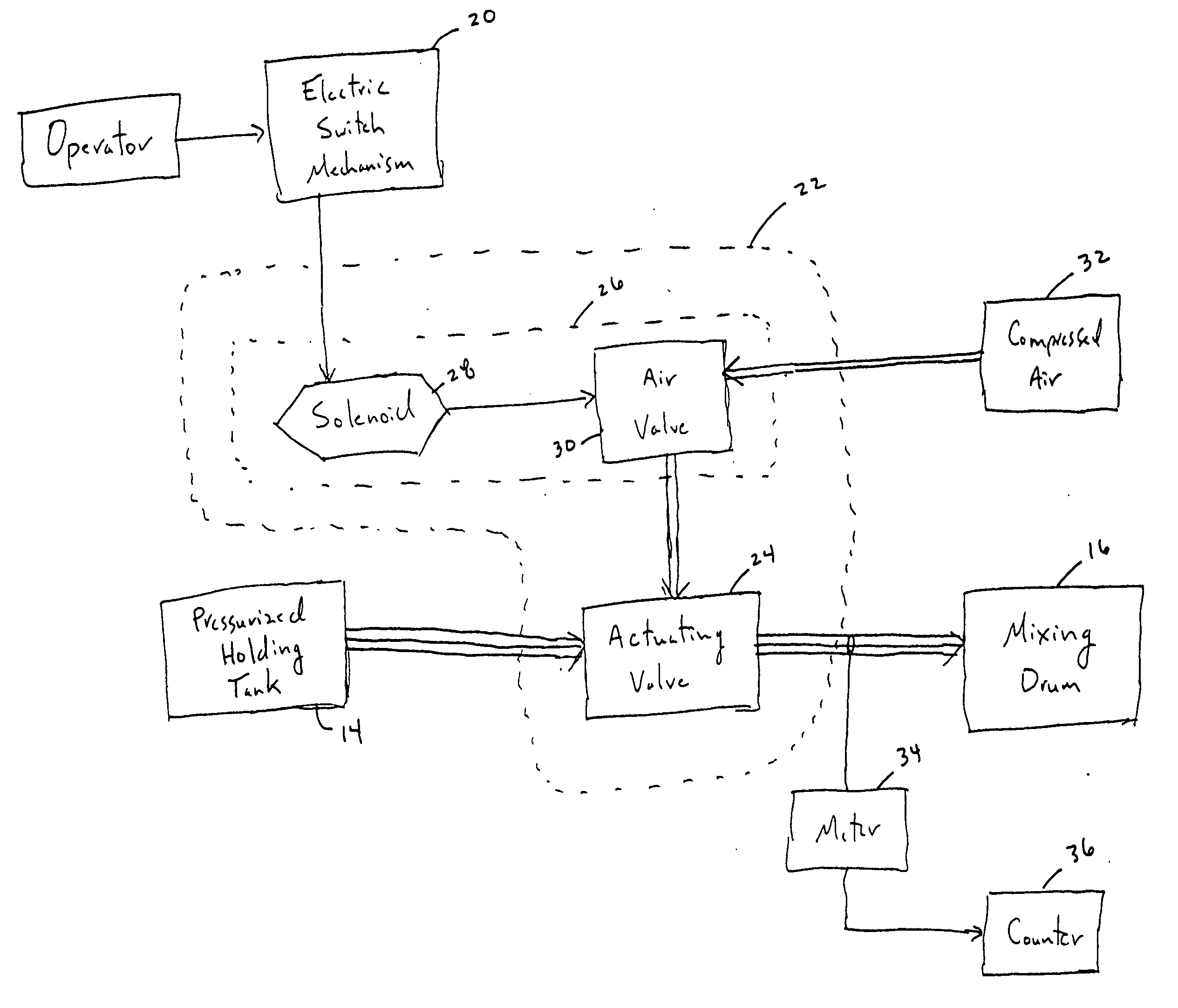
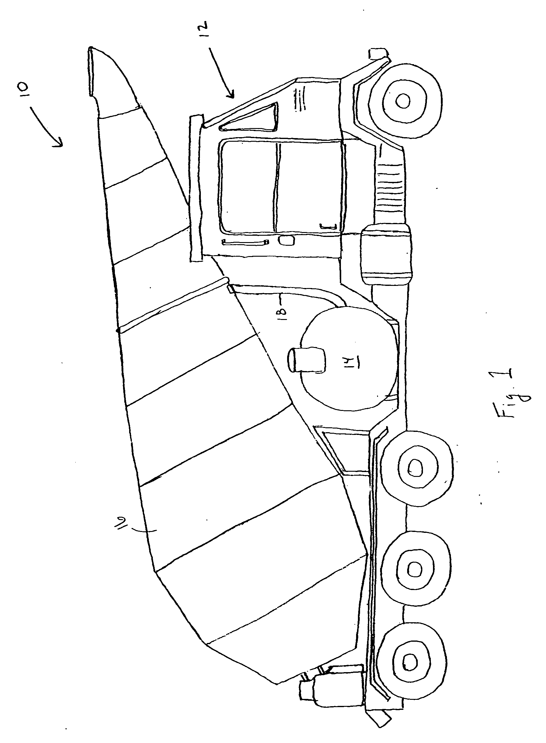
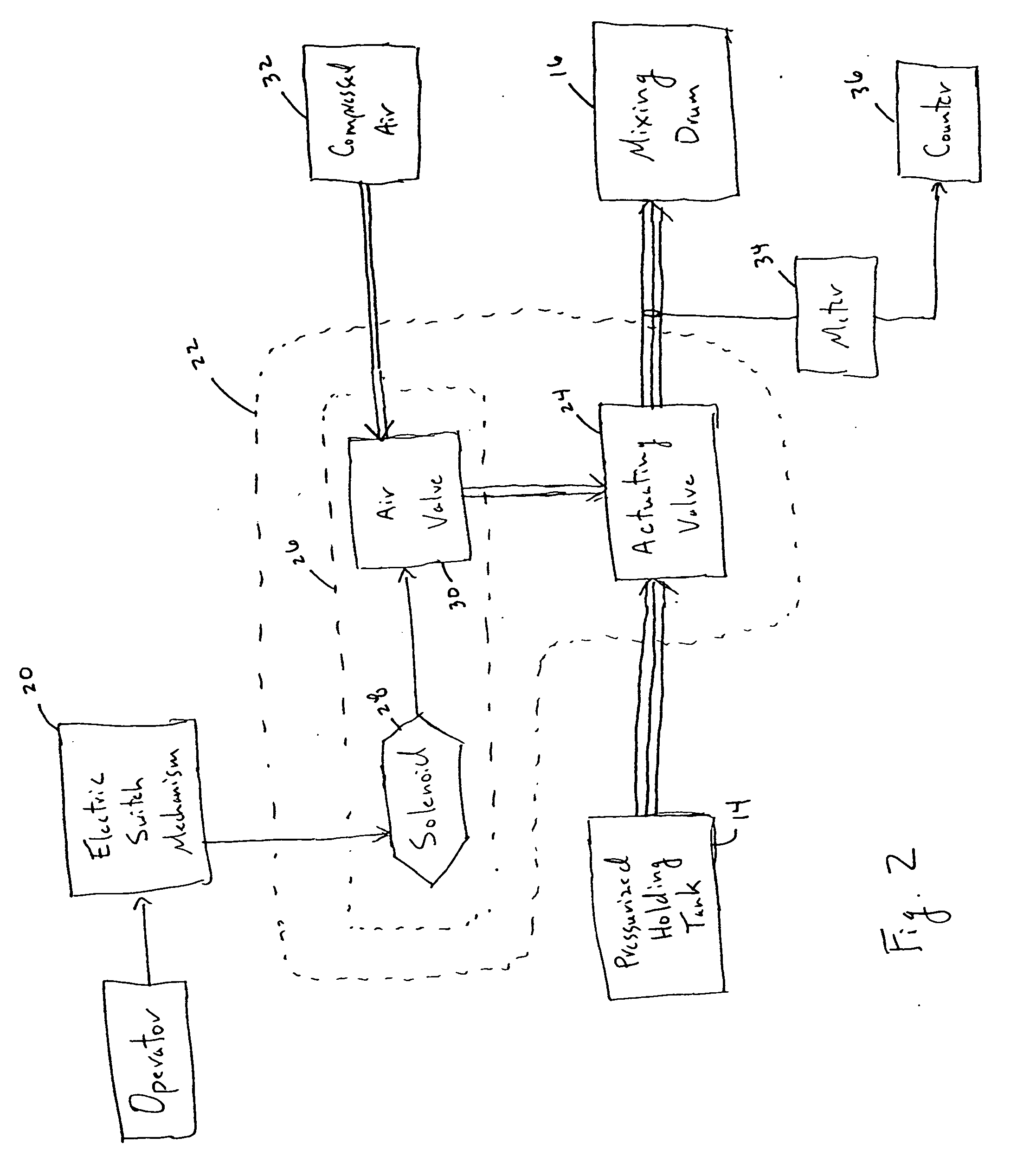
[0012] Exemplary embodiments of the present invention and its operation are hereinafter described in detail in connection with the views and examples of FIGS. 1-3, wherein like numbers indicate the same or corresponding elements throughout the views. As shown in FIG. 1, a vehicle 10 (e.g., concrete mixer) can have a cab portion 12, as well as a holding tank 14 and mixing drum 16 mounted on the vehicle 10. The vehicle 10 can be a front discharge concrete mixer like the embodiment illustrated in FIG. 1, but it is envisioned that the vehicle could also be a rear or side discharge concrete mixer. The cab portion 12 of the vehicle 10 effectively serves as the operating station for the release of the pressurized fluid. From the cab portion 12, the operator can actuate the release of the pressurized fluid from the holding tank 14 into the mixing drum 16. The holding tank 14 and the mixing drum 16 are operably connected by a conduit 18. In one exemplary embodiment, the conduit 18 can be a p...


PUM

PropertyMeasurementUnit
pressureaaaaaaaaaa
pressureaaaaaaaaaa
lengthaaaaaaaaaa

Abstract

A system and method of controlling the release of pressurized fluid in a concrete mixer. Particularly, a system and method employing an electric switch mechanism within a cab portion of a vehicle to provide operator access to control the amount of water added to the mixing drum of the vehicle.

Description

TECHNICAL FIELD [0001] The present invention relates generally to a system and method for controlling the release of pressurized fluid in a concrete mixer. Particularly, the system and method employ an electric switch mechanism within a cab portion of a vehicle to provide operator access to control the amount of water added to a mixing drum of the vehicle. BACKGROUND OF THE INVENTION [0002] A key component of virtually every construction site is concrete production. Most sites utilize traditional concrete mixers to provide the requisite concrete for a work site. Because of such high demand for the production of concrete and the need for meeting deadlines on the construction site, it is very important that the concrete being produced meets requisite specifications. One common problem for concrete production can be the insufficient or overabundance of water added to the concrete mixture. Such a problem can cause the final concrete product to fail to meet the requisite standards necess...

Claims


Application Information

Patent Timeline
Patent Type & Authority Applications(United States)
IPC IPC(8): B28C7/12B28C7/14
CPCB28C5/4231B60P3/16B28C7/12
Inventor GOFF, BRYAN HOWARDGOOD, MAX SCOTT
Owner INNOVATIVE CONCRETE PROD
Why Eureka
Try Eureka