Method and device for optical pressure measurement of a gas in a closed container

a technology of optical pressure measurement and closed container, which is applied in the direction of instruments, specific gravity measurement, mechanical means, etc., can solve the problems of inability to automate methods, increase expenditure, and time-consuming exact measurement of absorption lines, etc., and achieves simple and robust results

Active Publication Date: 2014-04-29
HEUFT SYSTTECHN GMBH
View PDF23 Cites 5 Cited by
  • Summary
  • Abstract
  • Description
  • Claims
  • Application Information

AI Technical Summary

Benefits of technology

[0007]The present invention is based on the objective to provide a method for optical pressure measurement of a gas in a closed container which is as simple and robust as possible, as well as a device for performing the method, which are also suited for industrial utilisation.
[0009]In difference to the methods known in the state of the art, in the method of the present invention there is no spectral analysis wherein a spectrally tunable laser is used in order to detect the position of the absorption line as accurately as possible. The method of the present invention is based on the finding that also the accumulated intensity of the detected radiation in the second wavelength range is a very accurate indicator for the pressure of the gas to be measured. This finding permits to provide a particularly simple and robust measurement method, wherein the radiator radiates in a first wavelength range, and the detector detects an accumulated intensity of the transmitted radiation.
[0015]In a particularly preferred embodiment, the second wavelength range of the detector in which the accumulated intensity is determined, comprises also the wavelength range in which there is an absorption of the radiation by the gas. It has proven that the pressure values determined according to the present invention are particularly reliable when the wavelengths that contribute to the accumulated value for the intensity are within the absorption spectrum.
[0020]Three utilisations of the method are particularly advantageous, because the conditions of the surroundings require a robust method. The first preferred possibility of utilisation is to direct the radiation through a closed beverage bottle. By doing so, the pressure of carbon dioxide in the bottle can be measured. The measurement is fast and reliable, and it can be used also in the filling process of bottles.
[0021]A further utilisation is to check a protective gas filling. In food technology in particular, protective gas fillings are used to improve the shelf life of food. In this, there is the need to check whether the protective gas has been correctly filled in. By using the method of the present invention, the pressure of the filling with protective gas or of a component thereof, respectively, can be detected reliably, whereby the correct addition of the protective gas filling is ascertainable.
[0023]The device of the present invention consists of a radiator, a detector and an analysing unit. The radiator generates a radiation in a first wavelength range, wherein the first wavelength range is selected such that there is an absorption of the radiation by the gas. Thus, the gas has at least one absorption line in the first wavelength range. The detector detects the intensity of the radiation transmitted through the container and the gas in a second wavelength range, wherein the second wavelength range overlaps at least partially with the first wavelength range. The analysing unit assigns a pressure value to the accumulated intensity of the detected radiation in the second wavelength range. For technical reasons, the step of accumulation is preferably done by the detector, which detects the accumulated intensity of the radiation directly over the second wavelength range. The device of the present invention can be produced in a cost-saving way with simple components which are suitable for the utilisation in the industry.

Problems solved by technology

Moreover, very precise control of the operating current and the operating temperature of the laser is necessary for this, which further increases the expenditure.
The exact measurement of an absorption line takes so much time that these methods are not suitable for automatization.
Thus, the method has only a limited measurement range and is intended for low pressures.

Method used


Image

  • Method and device for optical pressure measurement of a gas in a closed container
  • Method and device for optical pressure measurement of a gas in a closed container
  • Method and device for optical pressure measurement of a gas in a closed container

Examples


Embodiment Construction

[0035]While this invention may be embodied in many different forms, there are described in detail herein a specific preferred embodiment of the invention. This description is an exemplification of the principles of the invention and is not intended to limit the invention to the particular embodiment illustrated

[0036]For better understanding of the present invention, the basic physical principles of the optical pressure measurement of gases will be outline at first:

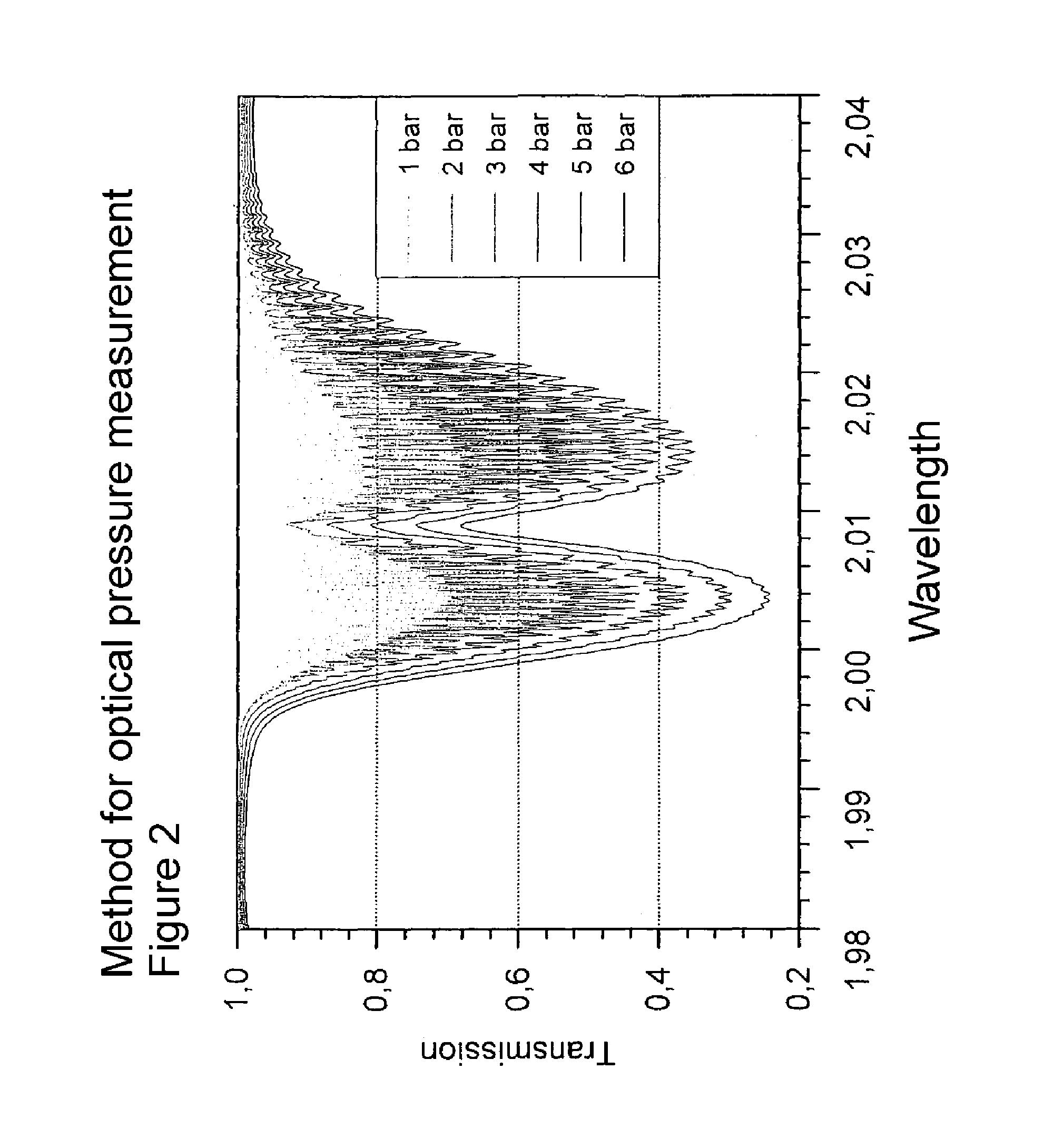
[0037]The optical pressure measurement is based on the absorption of electromagnetic radiation by molecules according to the law of Lambert and Beer

ITrans=I0exp(αd)

wherein ITrans is the transmitted intensity, I0 the radiated intensity, α the absorption coefficient and d the path length across the measurement volume. For the absorption coefficient depending on the frequency v we have:

α(v)=σ(v)N,

wherein N is the number of the absorbing molecules per volume and σ(v) is the wavelength-depending absorption cross section. From ...


PUM

PropertyMeasurementUnit
wavelengthsaaaaaaaaaa
wavelengthaaaaaaaaaa

Abstract

Method for optical pressure measurement of a gas in a closed container by directing a radiation of a radiator through the container and measuring the transmitted radiation by a detector, wherein the radiation of the radiator covers at least one first wavelength range in which there is an absorption of the radiation by the gas, the intensity of the transmitted radiation is detected in a second wavelength range by the detector, wherein the second wavelength range overlaps at least partially with the first wavelength range, and an accumulated intensity of the detected radiation in the second wavelength range is assigned to a pressure of the gas.

Description

CROSS-REFERENCE TO RELATED APPLICATIONS[0001]Not applicable.STATEMENT REGARDING FEDERALLY SPONSORED RESEARCH[0002]Not applicable.BACKGROUND OF THE INVENTION[0003]The present invention relates to a method and a device for optical pressure measurement of a gas in a closed container.[0004]For the measurement of the pressure in beverage bottles, methods based on repeated volume expansion are known (AT 409 673, GB 2,373,584, U.S. Pat. No. 6,874,351). These methods permit only random sampling measurements, because the beverage has to be filled into an extra measurement chamber. Even the pressure sensors placed into the bottles, known from DE 10 2007 027 708 A1 for instance, do not permit online / inline measurement. From DE 10 2006 001 902 B4, DE 10 2006 030 296 A1 and JP 00 2006 030 161 AA, methods in which the absorption line of the enclosed gas is measured with the aid of a laser are known for optical pressure measurement in the closed container. For this purpose, it must be ensured that...

Claims


Application Information

Patent Timeline
Patent Type & Authority Patents(United States)
IPC IPC(8): G01L9/00
CPCG01L11/02
Inventor BAUMANN, BERNDWOLFF, MARCUS
Owner HEUFT SYSTTECHN GMBH
Why Eureka
Try Eureka