
Wireless in-bore patient monitor for MRI

a patient monitor and in-bore technology, applied in the field of electronic patient monitors, can solve the problems of long cables, difficult to reach the patient, and the difficulty of conventional radio transmission in the mri environment, and achieve the effect of low error rate and high bandwidth at practical transmission power

Inactive Publication Date: 2006-09-14
INVIVO CORP
View PDF4 Cites 35 Cited by
  • Summary
  • Abstract
  • Description
  • Claims
  • Application Information

AI Technical Summary

Benefits of technology

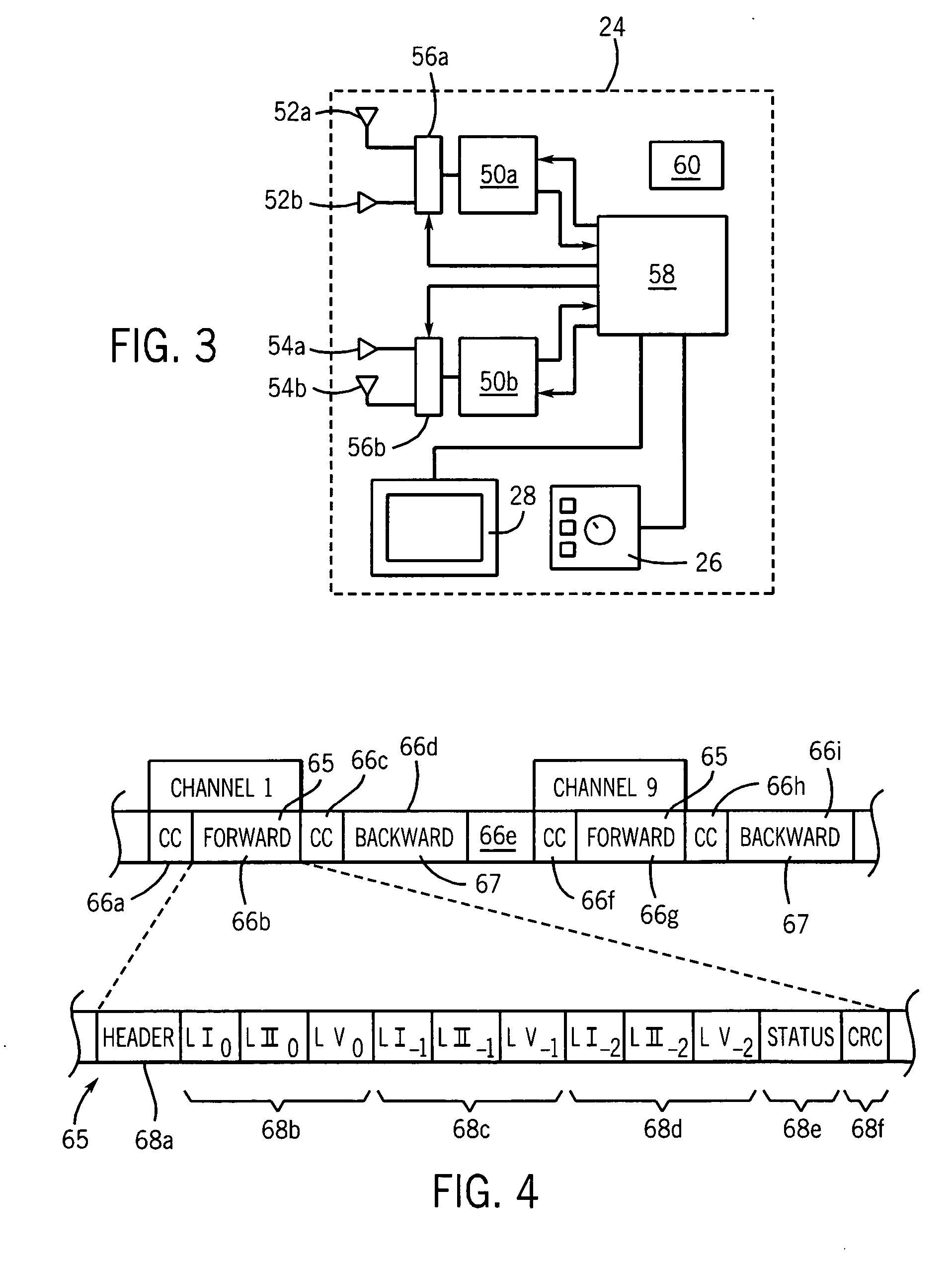
[0010] The present invention provides a wireless, in-bore patient monitoring system that provides the necessary high-data transmission rate and robustness against interference in an MRI environment. The invention addressed the difficult environment of MRI by using multiple diversity techniques including frequency diversity, antenna location diversity, antenna polarization diversity and time diversity in the transmitted signals. In the preferred embodiment of the invention, error detection codes attached to the signals or the signal quality of the signals are monitored to select among diverse pathways, dynamically, allowing low error rates and high bandwidth at practical transmission power.
[0014] It is another object of at least one embodiment of the invention to provide a simple and robust method of selecting among the diverse multiple channels to identify accurate data.
[0016] It is thus another object of at least one embodiment of the invention to use frequency diversity to eliminate potential sources of interference while nevertheless ensuring that the wireless frequencies do not interfere with the MRI machine's detection of NMR signals.
[0018] It is thus another object of at least one embodiment of the invention to provide maximum diversity with each communicating transmitter and receiver.
[0022] It is thus another object of at least one embodiment of the invention to provide a system avoiding dead zones caused by interfering reflections off the shielded magnet room wall.
[0026] It is thus another object of at least one embodiment of the invention to create a system robust against short-duration data losses without complex and time-consuming handshaking routines.

Problems solved by technology

Long runs of cables can be a problem because they are cumbersome and can interfere with access to the patient and free movement of personnel about the magnet itself.
Desirably, a wireless method of monitoring a patient in the MRI magnet bore would be developed, however, conventional radio transmission faces severe obstacles in the MRI environment.
First, the bore of the magnet itself is shielded, restricting the free transmission of radio signals.
Second, the frequency and strength of wireless transmissions must be limited to prevent interference with the faint magnetic resonance signals detected by the MRI machine and to accommodate practical battery-powered operation of the transmitter.
Third, the radio frequency excitation pulse, that is part of the MRI process, can interfere with wireless transmissions.
Finally, the room in which the MRI machine is held may be shielded electrically and magnetically creating problems of reflection of wireless signals such as can produce “dead spots” in the room.
These problems are compounded by the requirement that patient signals, unlike voice signals, for example, must be robust and reliable in real time, even in the face of interference.
Particularly, when monitoring signals are used to gate the MRI machine, even short periods of signal dropout or delay are unacceptable.
Accordingly, conventional wireless transmission techniques may prove impractical.

Method used


Image

  • Wireless in-bore patient monitor for MRI
  • Wireless in-bore patient monitor for MRI
  • Wireless in-bore patient monitor for MRI

Examples


Embodiment Construction

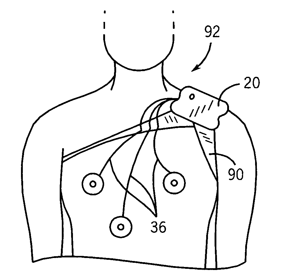
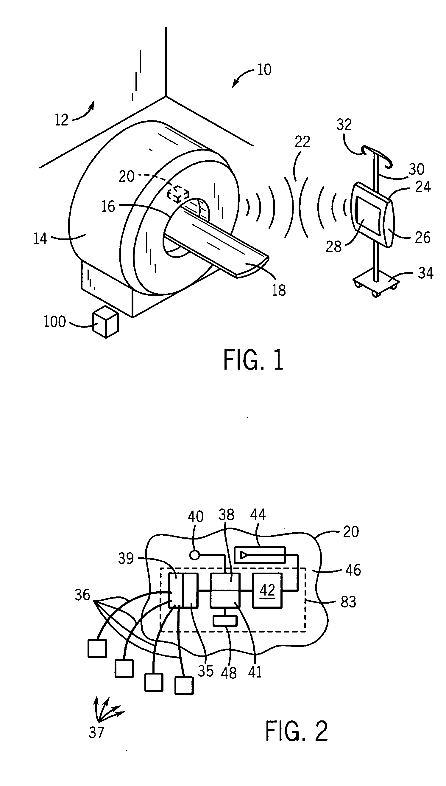
[0043] Referring now to FIG. 1, an MRI magnet room 10 containing an MRI magnet 14 may have shielded walls 12 blocking and reflecting radio waves. The MRI magnet 14 may have a central bore 16 for receiving a patient (not shown) supported on a patient table 18. As used henceforth, bore shall refer generally to the imaging volume of an MRI machine and should be considered to include the patient area between pole faces of open frame MRI systems.

[0044] During the MRI scan, the patient is held within the bore 16 and may be monitored via wireless patient unit 20 attached to the patient or patient table 18 and within the bore 16 during the scan. The patient unit 20 transmits via radio waves 22 physiological patient data and status data (as will be described) to processing unit 24 outside the bore 16 useable by personnel within the magnet room 19. The processing unit 24 typically will include controls 26 and a display 28 providing an interface for the operator, and may be usefully attached ...


PUM


Abstract

A wireless in bore sensor for magnet resonance imaging provides radio frequency communication of physiological and other data signals from a battery powered unit held adjacent to the patient within the bore by using multiple diversity techniques to overcome the interfering environment of the MRI imaging system and to prevent interference with the MRI system.

Description

CROSS-REFERENCE TO RELATED APPLICATIONS [0001]—STATEMENT REGARDING FEDERALLY SPONSORED RESEARCH OR DEVELOPMENT [0002]—BACKGROUND OF THE INVENTION [0003] The present invention relates generally to electronic patient monitors, and in particular, to a wireless patient monitor suitable for use in the severe electromagnetic environment of a magnetic resonance imaging machine. [0004] Magnetic resonance imaging (MRI) allows images to be created of soft tissue from faint electrical resonance signals (NMR signals) emitted by nuclei of the tissue. The resonance signals are generated when the tissue is subjected to a strong magnetic field and excited by a radio frequency pulse. [0005] The quality of the MRI image is in part dependent on the quality of the magnetic field, which must be strong and extremely homogenous. Ferromagnetic materials are normally excluded from the MRI environment to prevent unwanted forces of magnetic attraction on these materials and distortion of the homogenous field ...

Claims


Application Information

Patent Timeline
IPC IPC(8): A61B5/05
CPCA61B5/0006G01R33/283A61B5/0013A61B5/04085A61B5/282
Inventor WEEKS, ARTHUR R. JR.FISHER, STEPHEN DOUGLASKILDEN-PEDERSEN, JORGENHARWELL, ROBERT A.NOLAN, SCOTTMOORE, JOHN C.
Owner INVIVO CORP
Learn More