Electrical connector assembly

a technology of electrical connectors and connector assemblies, which is applied in the direction of vehicle connectors, coupling device connections, engagement/disengagement of coupling parts, etc., can solve the problems of difficult mating and unmating access to the connectors, and high manufacturing costs, and achieves simple and robust, easy to mating, and easy to align. , the effect of simple alignmen

Active Publication Date: 2006-08-22
APTIV TECH LTD
View PDF9 Cites 36 Cited by
  • Summary
  • Abstract
  • Description
  • Claims
  • Application Information

AI Technical Summary

Benefits of technology

[0006]The present invention provides an electrical connector assembly and a method of mating the same. The electrical connector assembly includes a panel sub-assembly which mates to at least one electrical connector body. Preferably two cam leveraging devices which rotate in opposing directions are mounted rotatably to the panel sub-assembly for sliding engagement of respective cam studs engaged rigidly to the electrical connector body. Opposing rotations of the cam leveraging devices along respective and parallel rotation axes causes the panel sub-assembly to move linearly along a mating axis disposed orthogonally to the rotation axes and toward the electrical connector body to a staged position. During linear panel sub-assembly movement from the disconnected position to the staged position, the cam studs slide against a first portion of a track carried by respective cam levers and which generally spirals radially inward toward the rotation axis. Reversing rotation of both cam leveraging devices causes the panel sub-assembly to continue linear movement toward the electrical connector body from the staged position and to a mated position. During linear panel sub-assembly movement from the staged position to the mated position, the cam stud lifts off of the first portion, and is caught by and slides along a second portion of the track to a mated end.
[0007]Objects, features and advantages of this invention include a cam levered electrical connector assembly which is easily aligned for mating, is capable of smooth and relatively easy mating and unmating of an electrical connection, utilizes cam levers which require minimal rotation in any one direction yet produce an appreciable amount of linear movement along a mating axis and without producing any moments or normal forces with respect to the mating axis. Further advantages include a relatively simple, robust and inexpensive design being maintenance free and having a long and useful life.

Problems solved by technology

Unfortunately, due to this orientation, access to the connectors is often difficult for mating and unmating.
Unfortunately, the panel, trays and connector bodies are all held together by a plurality of threaded fasteners which is costly to manufacture and requires special tools for assembly and maintenance purposes.

Method used


Image

  • Electrical connector assembly
  • Electrical connector assembly
  • Electrical connector assembly

Examples


Embodiment Construction

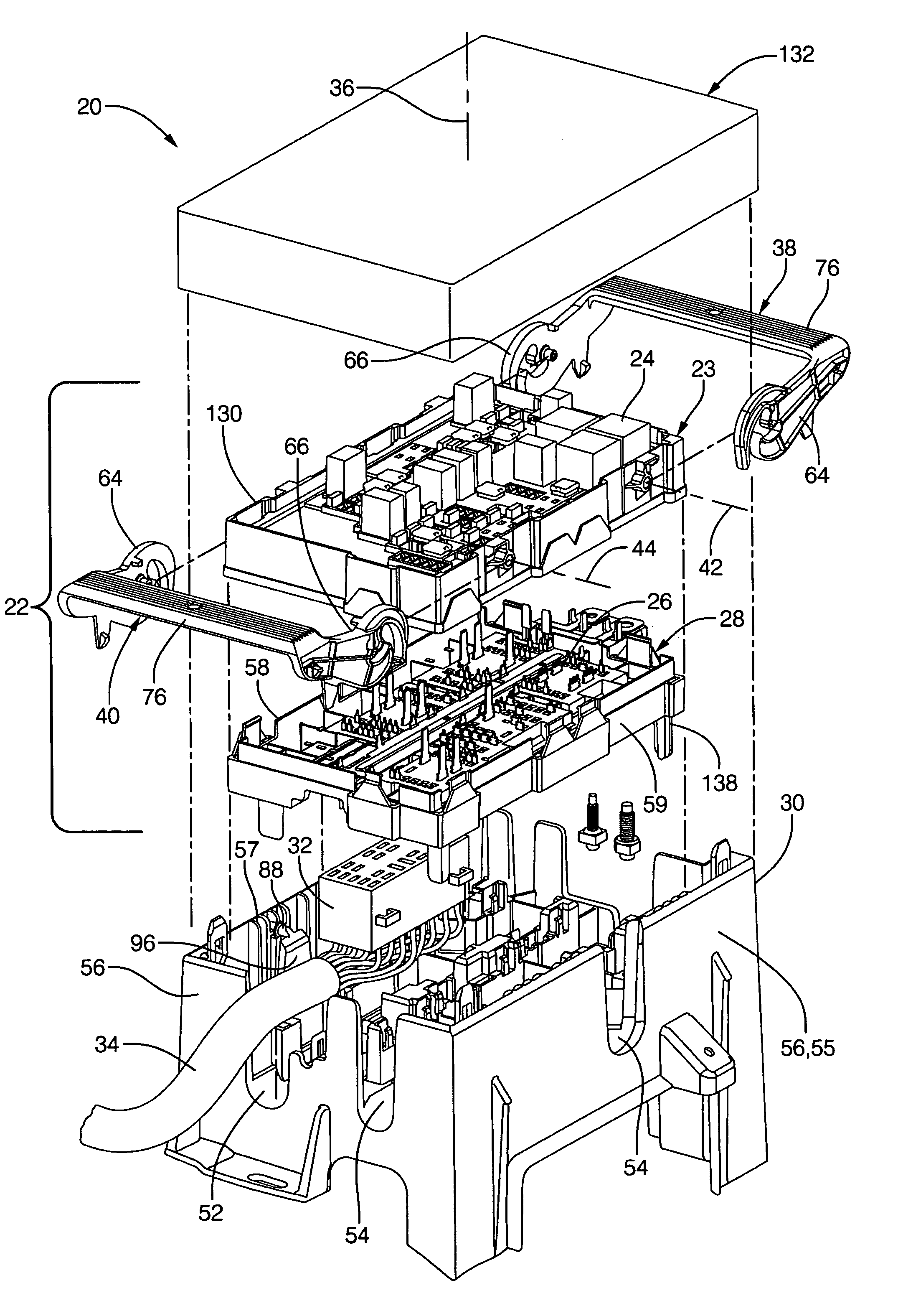
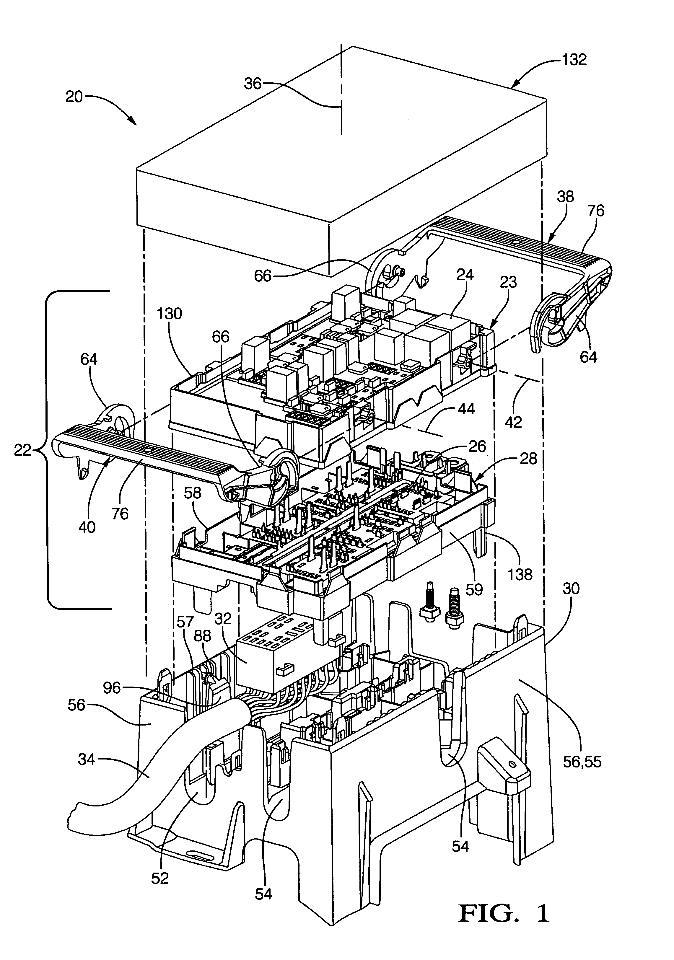
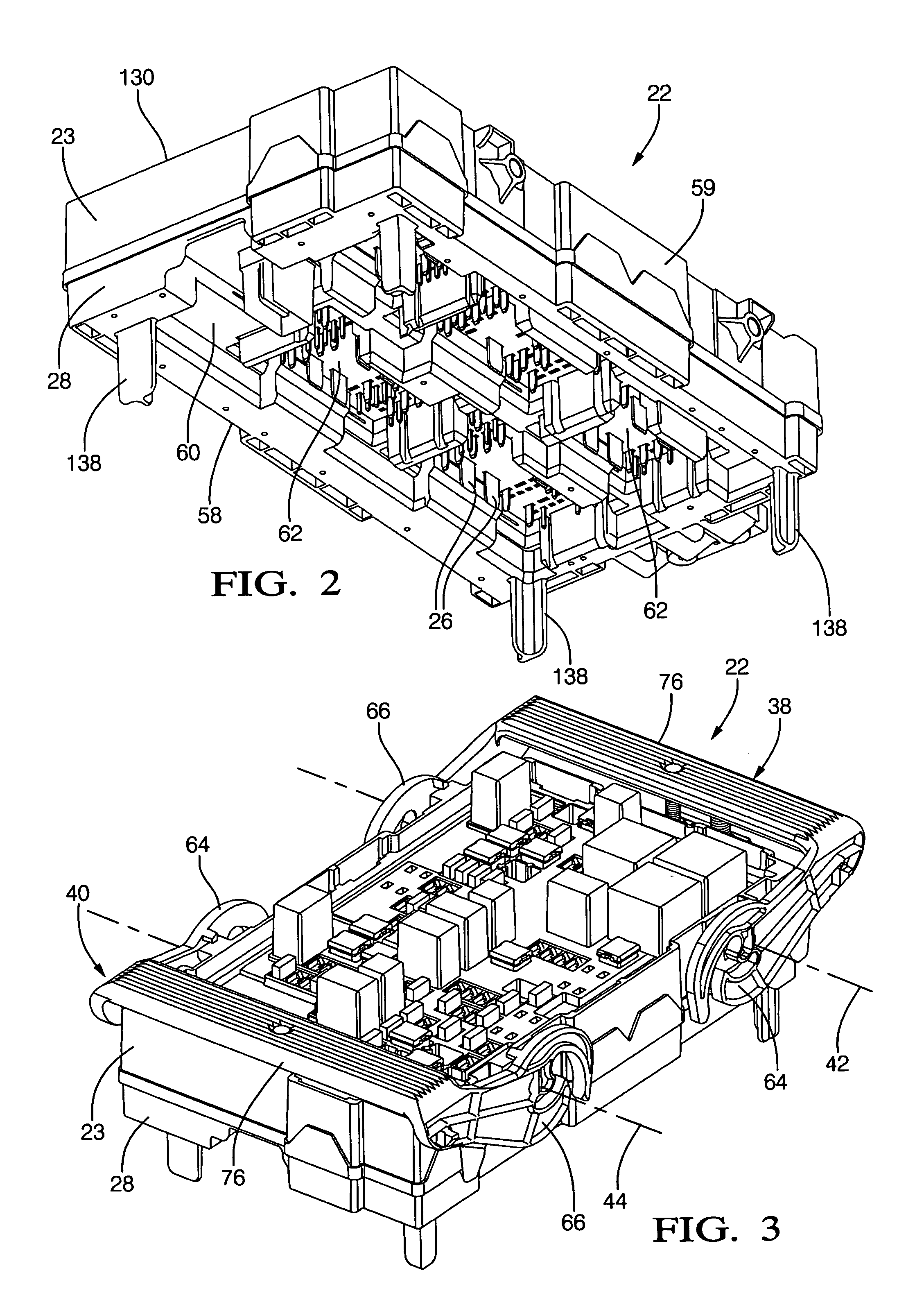
[0021]Referring to the figures wherein like numerals refer to like elements throughout the several views, FIG. 1 illustrates a preferred embodiment of an electrical connector assembly 20 of the present invention. The electrical connector assembly 20 is preferably an electrical distribution center, but can also be any device which makes an electrical connection including an electrical connector. The electrical connector assembly 20 is shown as an electrical distribution center preferably having an electrical panel sub-assembly 22 having a panel 23 supporting electrical relays, fuses, control modules, and / or terminals 24 which are preferably mated to a series of substantially vertical male terminals 26 supported by a mid tray 28 of the sub-assembly 22 located beneath and pre-engaged to the panel 23. If the electrical connector assembly 20 is a simpler electrical connector, the panel 23 and tray 28 are preferably injection molded as one unitary plastic piece which supports terminals 24...


PUM


Abstract

The present invention provides an electrical connector assembly and a method of mating the same. The electrical connector assembly includes a panel sub-assembly which mates to at least one electrical connector body. Preferably two cam leveraging devices which rotate in opposing directions are mounted rotatably to the panel sub-assembly for sliding engagement of respective cam studs engaged rigidly to the electrical connector body. Opposing rotations of the cam leveraging devices along respective and parallel rotation axes causes the panel sub-assembly to move linearly along a mating axis disposed orthogonally to the rotation axes and toward the electrical connector body to a staged position. During linear panel sub-assembly movement from the disconnected position to the staged position, the cam studs slide against a first portion of a track carried by respective cam levers and which generally spirals radially inward toward the rotation axis. Reversing rotation of both cam leveraging devices causes the panel sub-assembly to continue linear movement toward the electrical connector body from the staged position and to a mated position. During linear panel sub-assembly movement from the staged position to the mated position, the cam stud lifts off of the first portion, and is caught by and slides along a second portion of the track to a mated end.

Description

FIELD OF THE INVENTION[0001]The present invention relates generally to electrical connector assemblies, and more to methods for mating electrical connector assemblies.BACKGROUND OF THE INVENTION[0002]Electrical connector assemblies, such as a simple electrical connector or a multi-functional electrical distribution center, are widely used. The electrical distribution centers are generally a central junction box or block system designed as a stand-alone assembly. The electrical connectors typically electrically connect at least two wire harnesses together and thus house a plurality of mated male and female terminals. The distribution centers perform a similar function as the electrical connectors, but may also house various fuses, relays and other electrical devices in a central location. Electrical distribution centers not only reduce cost by consolidating various functions and / or electrical connections into one block, but the centers also reduce the number of cut and spliced leads ...

Claims


Application Information

Patent Timeline
Patent Type & Authority Patents(United States)
IPC IPC(8): H01R13/62
CPCH01R9/2425H01R9/2458H01R13/6295H01R13/62966H01R13/62938H01R9/2491H01R13/447H01R2201/26H01R13/62955H01R13/623H01R13/629
Inventor SENK, JOSEPH M.REEDY, PATRICK J.BLASKO, RAYMOND J.DAGGETT, BARRY M.
Owner APTIV TECH LTD
Why Eureka
Try Eureka