

Adaptive pre-filtering system
- Summary
- Abstract
- Description
- Claims
- Application Information
AI Technical Summary
Benefits of technology
Problems solved by technology
Method used
Image

Examples
Embodiment Construction
[0028] In the following description, details are provided to describe the preferred embodiments of the invention. It shall be apparent to one skilled in the art, however, that the embodiments may be practiced without such details. Some of these details may not be described at length so as not to obscure the preferred embodiments.
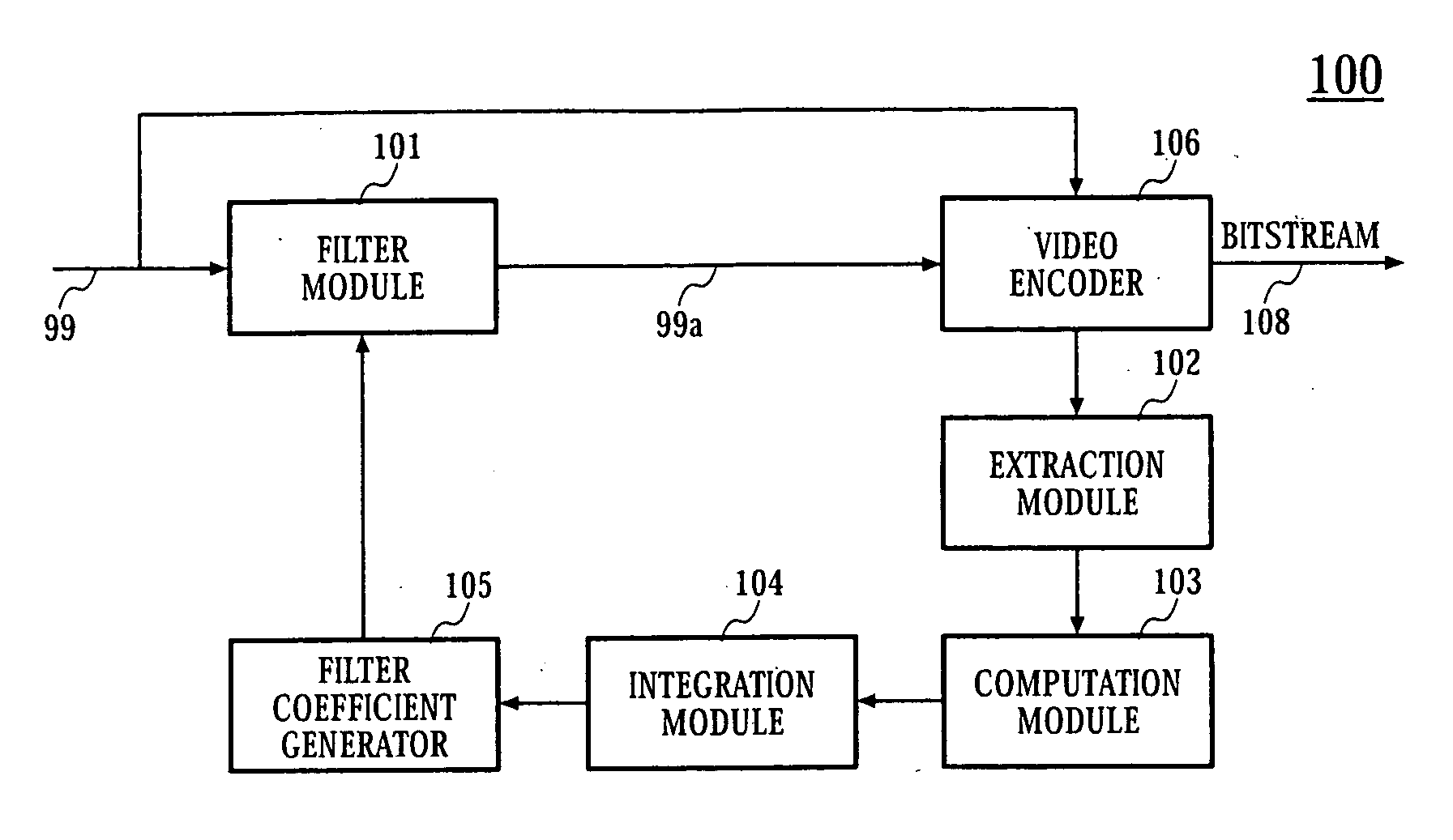
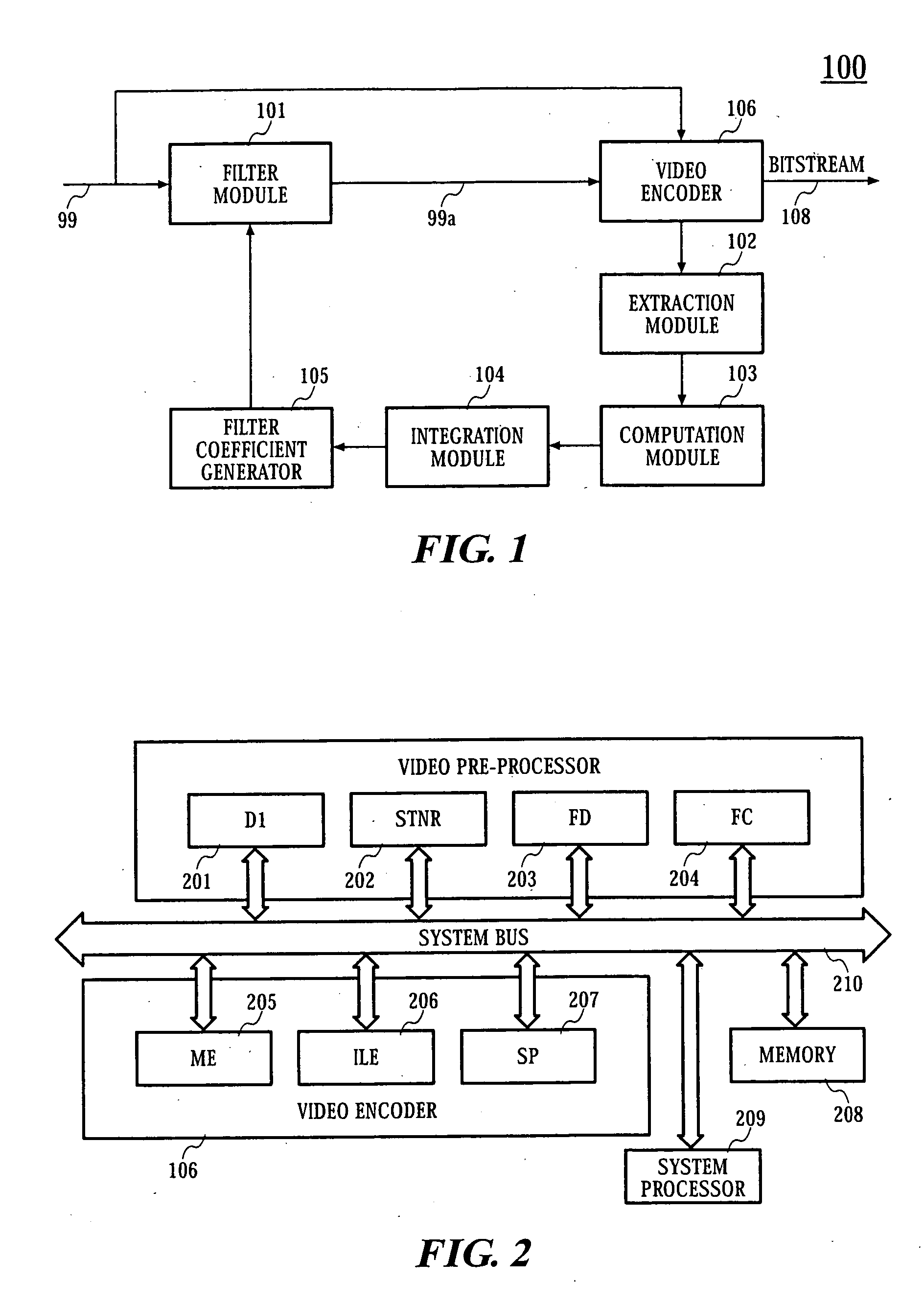
[0029] Adaptive pre-filtering of video data reduces video data complexity by filtering and thus enables ease of encoding of video data by video encoders. Video artifacts like blocking and ringing which are pre-dominant in low bit rate applications may thus be reduced. Filtering of pre-encoded images to reduce encoding complexity is thus used to improve the visual quality of video by using smaller quantization step size.
[0030] Referring to FIG. 7, the present embodiment discloses a method for adaptive pre-filtering comprising the steps of:
[0031] extracting tuning parameters from video encoding process;
[0032] processing these tuning parameters to generate ...
PUM
 Abstract
Description
Claims
Application Information