Network configuration method allotting channels to wireless stations by generating a broadcast tree

a network configuration and wireless station technology, applied in the direction of broadcast service distribution, network topologies, electrical appliances, etc., can solve the problems of insufficient bandwidth for each wireless station, insufficient coverage of the network, and more overhead

Inactive Publication Date: 2007-03-22
OKI ELECTRIC IND CO LTD
View PDF3 Cites 6 Cited by
  • Summary
  • Abstract
  • Description
  • Claims
  • Application Information

AI Technical Summary

Benefits of technology

[0008] It is an object of the present invention to provide a wireless communication system and a network configuration control method that may effectively allocate channels to adjacent wireless stations and may need minimum modification of the channels.
[0011] In accordance with the present invention, in addition to the common channel being allocated to the wireless stations, a different subchannel is allocated to each of the blocks or groups of the wireless station. The adjacent wireless stations may thus be effectively allocated to the channels, including subchannels. The allocation of the common channel and subchannels may need minimum modification of the communication channels.

Problems solved by technology

The conventional technology, however, is not adapted to comply with the environment of wireless multi-hop networks.
In the wireless multi-hop network, such wireless stations are connected in the form of multiple stages, and the necessity of parallel communications with neighbor wireless stations is extensive, so that it is often insufficient to provide each wireless station with two channels available.
Changing the allocated channels in a broader service area may cause more overhead.

Method used


Image

  • Network configuration method allotting channels to wireless stations by generating a broadcast tree
  • Network configuration method allotting channels to wireless stations by generating a broadcast tree
  • Network configuration method allotting channels to wireless stations by generating a broadcast tree

Examples


Embodiment Construction

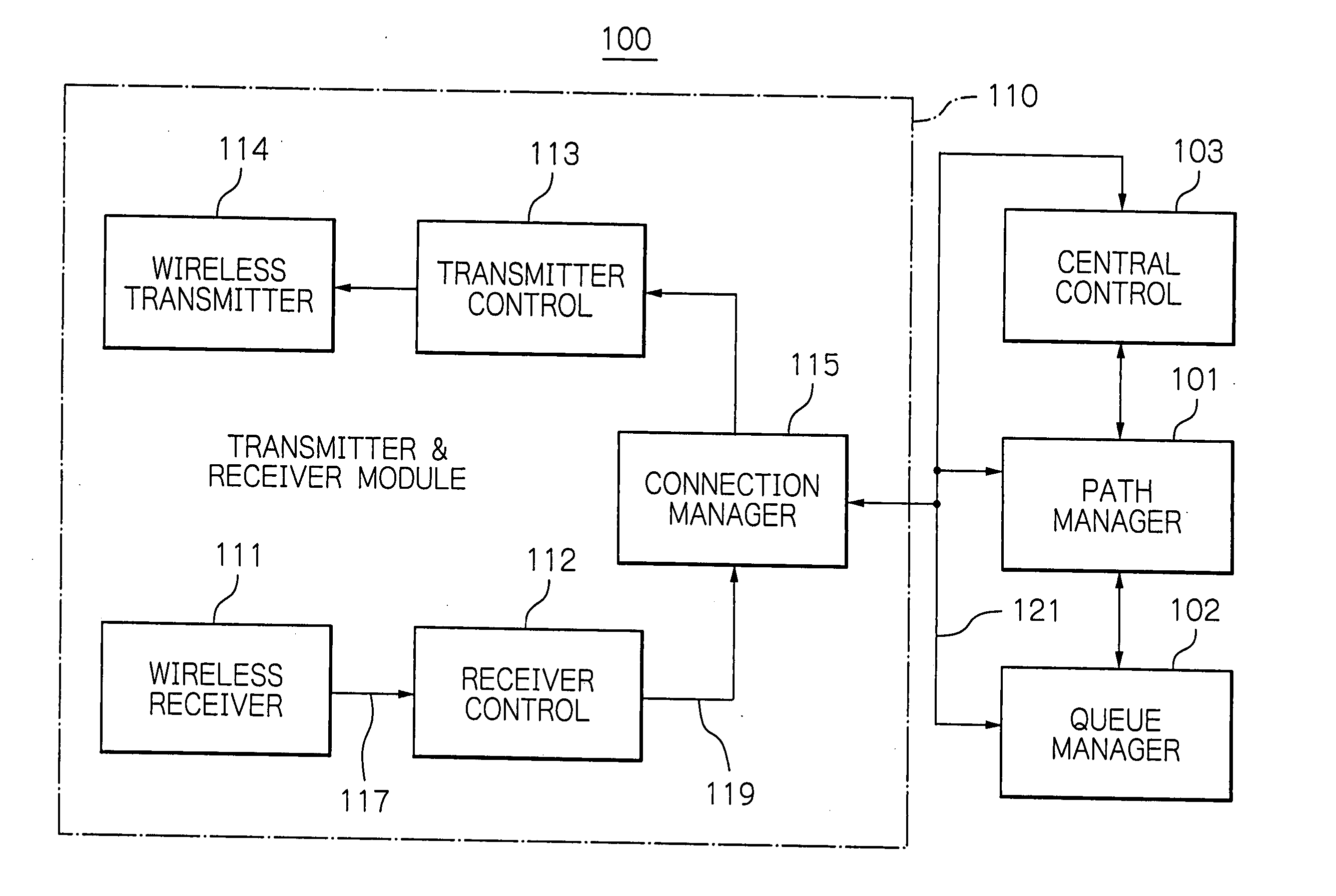
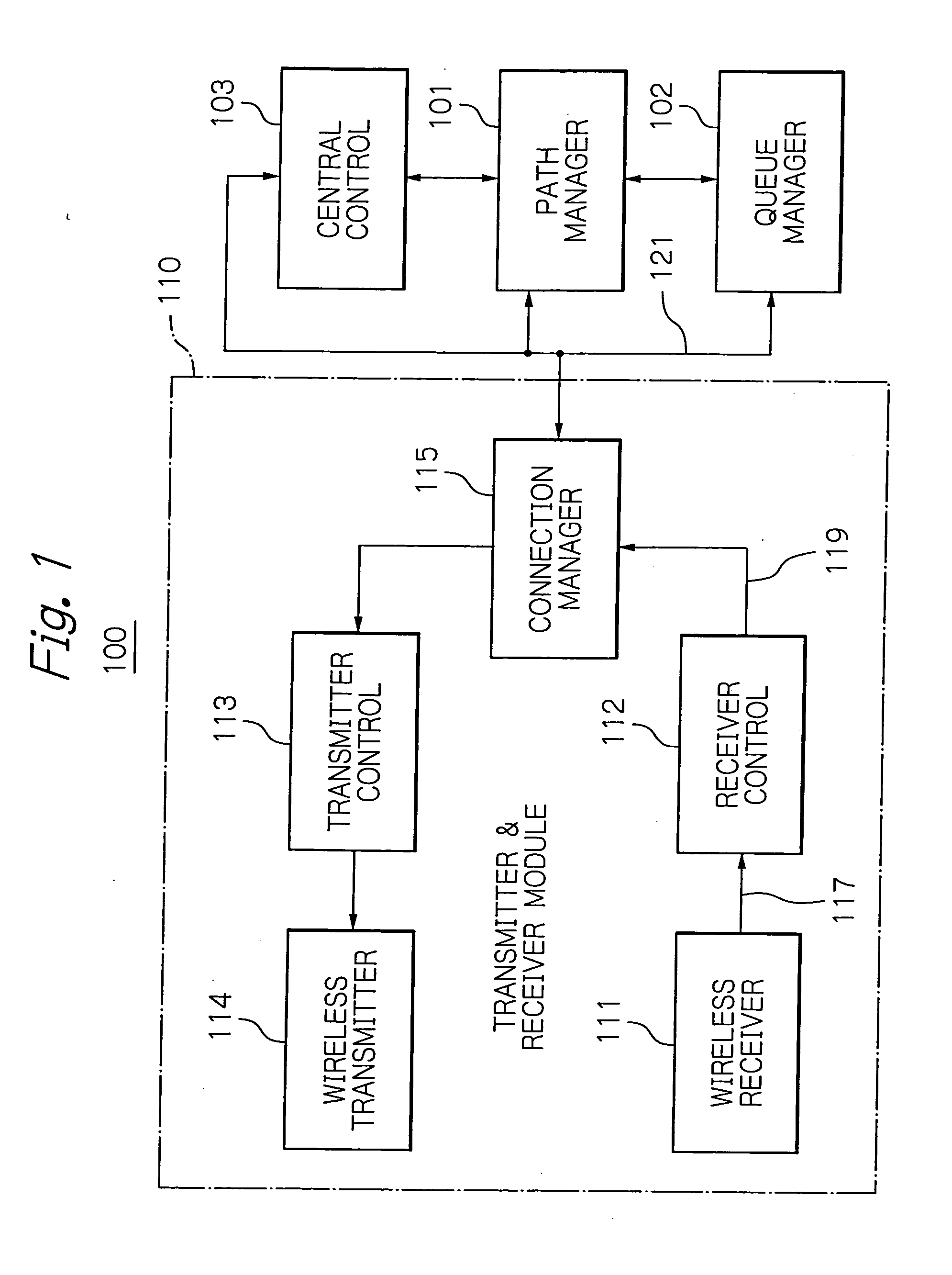
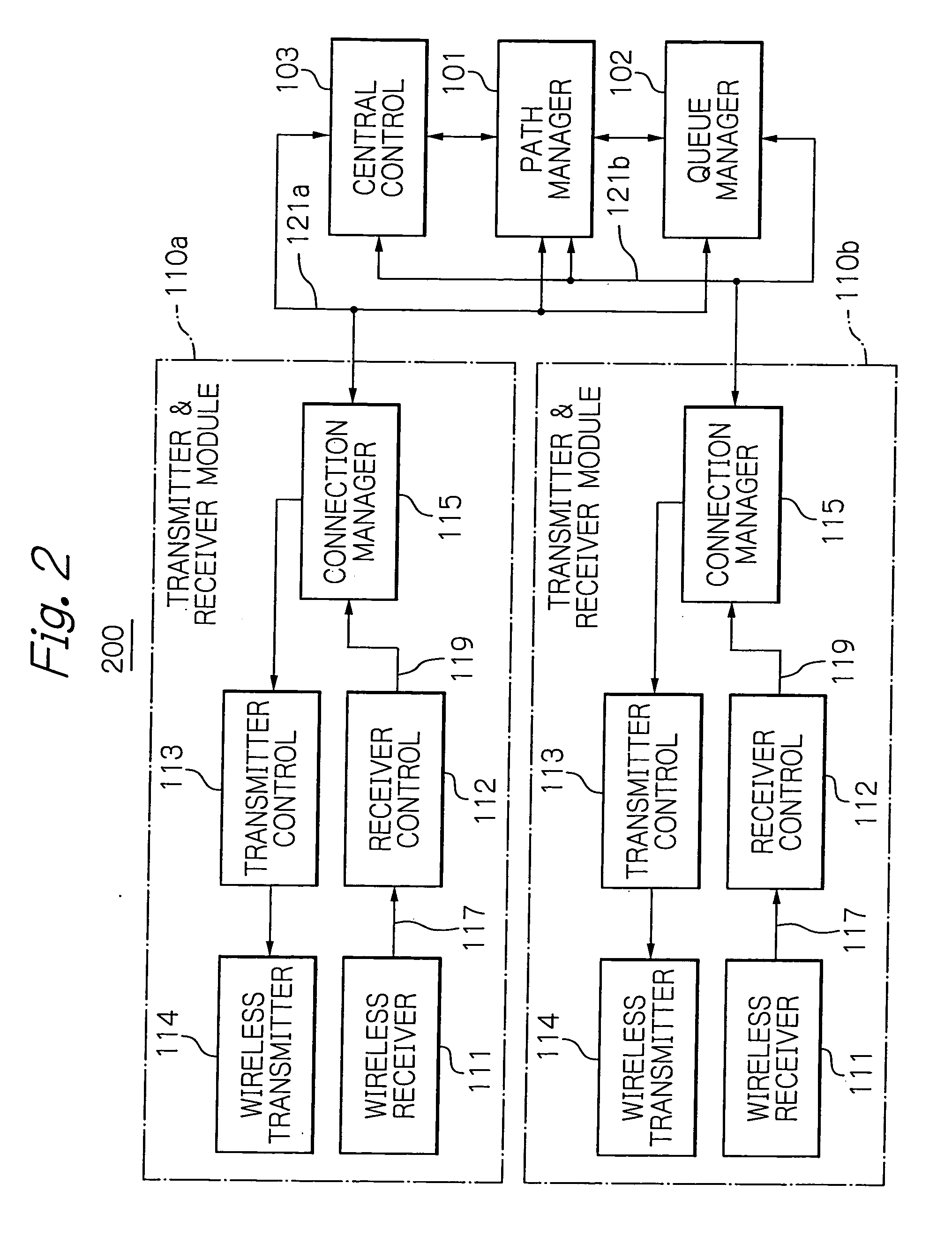
[0028] With reference to the accompanying drawings, a description will be given below on the wireless communication system of an illustrative embodiment according to the present invention. FIGS. 1 and 2 are schematic block diagrams showing the basic configuration of a wireless station according to an embodiment of the present invention. More specifically, FIG. 1 depicts the basic configuration of a wireless station 100 including a single transmitter and receiver module 110. FIG. 2 shows the basic configuration of a wireless station 200 including a couple of transmitter and receiver modules 110a and 110b. In the application, like components are designated with the same reference numerals with repetitive description thereon being refrained from for avoiding redundancy.

[0029] As shown in FIG. 1, the wireless station 100 includes a path manager 101, a queue manager 102, a central control 103 and the single transmitter and receiver module 110, which are interconnected as illustrated. In...


PUM


Abstract

All wireless stations included in a wireless multi-hop network are allocated to one of channels available to the network as a common channel. A broadcast tree beginning from any one of the wireless stations is generated based on link information including path information on all links formed between two wireless stations communicatable in one hop. Branch information of the generated broadcast tree is used to group all of the wireless stations into blocks, and to each block is allocated a subchannel different from the common channel. A wireless station that can use the channels has its subchannel to a subchannel of group to which it belongs. Adjacent wireless stations in a wireless multi-hop network may thus be effectively allocated to communication channels, and may need minimum modification of the channels.

Description

BACKGROUND OF THE INVENTION [0001] 1. Field of the Invention [0002] The present invention relates to a wireless communication system and a network configuration method, which are particularly applicable to, for example, a wireless multi-hop network that is constructed according to an autonomous distributed control. Specifically, the present invention relates to a method of controlling a network configuration that connects, with a plurality of channels, wireless stations to each other, each of the wireless stations including one or more radio-frequency (RF) modules, or transmitter and receiver modules. [0003] 2 Description of the Background Art [0004] Japanese application patent laid-open publication No. 290229 / 1998 discloses a conventional feature that uses multiple channels to thereby increase the amount of communication conveyable. This publication proposes scanning of channels to detect a carrier and select the optimum channel, or the like. [0005] Further, there has already been ...

Claims


Application Information

Patent Timeline
Patent Type & Authority Applications(United States)
IPC IPC(8): H04Q7/20H04W4/06H04W72/04
CPCH04W4/06H04W84/18H04W72/04
Inventor KADO, YOUITI
Owner OKI ELECTRIC IND CO LTD
Why Eureka
Try Eureka