Methods and apparatuses for dynamic thermal control

a dynamic thermal control and apparatus technology, applied in the field of data processing systems, can solve the problems of system cooling, system not being able to continuously run worst-case workloads naturally, and tighter thermal budgets of computer systems

Active Publication Date: 2007-03-22
APPLE INC
View PDF98 Cites 143 Cited by
  • Summary
  • Abstract
  • Description
  • Claims
  • Application Information

AI Technical Summary

Benefits of technology

[0006] Methods and apparatuses for dynamically budgeting power usage to control temperatures in a data processing system are described here. Some embodiments of the present invention are summarized in this section.

Problems solved by technology

As the operating power consumptions of the individual components of computer system creep upwards, the thermal budgets of the computer systems have become tighter.
The systems have become more difficult to cool.
It is now becoming a challenge to design a computer system to run continuously the worst-case thermal load while pursuing other high performance goals, such as high computing power, compactness, quietness, better battery performance, etc.
For example, the systems may no longer be capable of continuously running worst-case workloads naturally without key parts of the system getting too hot.
For example, portable computer systems, such as laptop computers, have a compact housing and limited cooling capability; and thus a worst-case thermal load for a given cooling capability may limit the performance of the system because the worst-case thermal load may rarely occur and yet the system has been designed to sustain the continuous worst-case thermal load.
This may mean that the laptop is larger to provide more cooling capability even though the worst-case thermal load may rarely occur.

Method used


Image

  • Methods and apparatuses for dynamic thermal control
  • Methods and apparatuses for dynamic thermal control
  • Methods and apparatuses for dynamic thermal control

Examples


Embodiment Construction

[0040] The following description and drawings are illustrative of the invention and are not to be construed as limiting the invention. Numerous specific details are described to provide a thorough understanding of the present invention. However, in certain instances, well known or conventional details are not described in order to avoid obscuring the description of the present invention. References to one or an embodiment in the present disclosure are not necessarily references to the same embodiment; and, such references mean at least one.

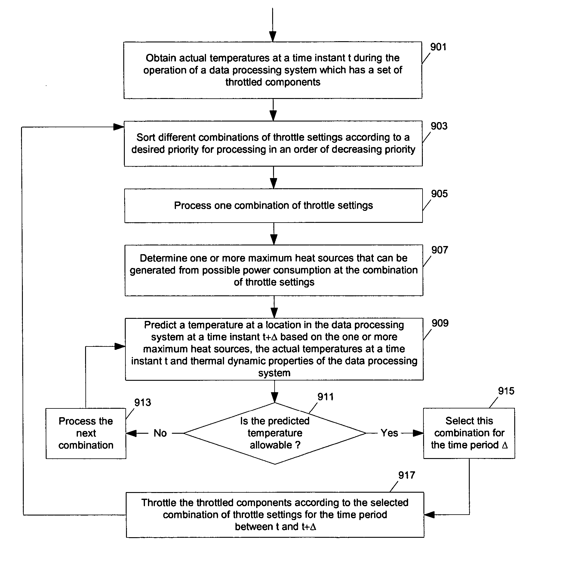
[0041] One embodiment of the present invention uses thermal throttling to allow a system to run under the dynamically determined thermal budget so that the system can operate in an appropriate operating setting under the dynamically determined thermal limit for the current workload, even if the system may not be capable of sustaining a worst-case workload under certain normal usage conditions.

[0042] In the prior art, the computer systems were ty...


PUM

PropertyMeasurementUnit
temperatureaaaaaaaaaa
voltageaaaaaaaaaa
frequencyaaaaaaaaaa

Abstract

Methods and apparatuses for dynamically budgeting power usage to control temperatures in a data processing system. In one aspect, a data processing system includes: a first sensor to determine an ambient temperature of an environment in which the data processing system is; and a controller (e.g., a microcontroller or a microprocessor) coupled to the sensor to control operations of the data processing system according to the ambient temperature. In one example, the data processing system further includes a second sensor to determine an actual temperature of a component of the data processing system. In one example, a controller is coupled to the temperature sensors to determine an operating setting of the data processing system based on a prediction of a temperature of the data processing system which is a function of the plurality of actual temperatures and the operating setting of the data processing system.

Description

TECHNOLOGY FIELD [0001] At least some embodiments of the present invention relate generally to data processing systems, and more particularly but not exclusively to the management of temperatures in data processing systems. BACKGROUND [0002] Traditionally, computer systems are designed to be able to continuously run a fairly worst-case thermal load corresponding to a worst-case workload. Design according to such a continuous worst-case load has never been much of a problem, because traditionally the individual components have had modest operating power consumptions and the computer systems have had considerable cooling capacity so that the systems could sustain the load fairly naturally. [0003] As the operating power consumptions of the individual components of computer system creep upwards, the thermal budgets of the computer systems have become tighter. The systems have become more difficult to cool. It is now becoming a challenge to design a computer system to run continuously th...

Claims


Application Information

Patent Timeline
Patent Type & Authority Applications(United States)
IPC IPC(8): G01K1/00G06F1/00
CPCG06F1/206
Inventor CONROY, DAVID G.COX, KEITH ALANCULBERT, MICHAEL
Owner APPLE INC
Why Eureka
Try Eureka