Method and Apparatus For Vehicle Service System Optical Target

a technology for vehicle service systems and optical targets, applied in the direction of mechanical measuring arrangements, instruments, mechanical means, etc., can solve the problems of increased cost and construction costs, increased clamping force, and increased cost and complication of adaptor systems

Active Publication Date: 2007-03-29
HUNTER ENG
View PDF19 Cites 41 Cited by
  • Summary
  • Abstract
  • Description
  • Claims
  • Application Information

AI Technical Summary

Benefits of technology

[0014] Briefly stated, the present invention provides a machine vision vehicle wheel alignment system optical target assembly which incorporates an adaptor for attachment of an optical target to a vehicle wheel assembly. The adaptor includes at least one fixed contact point for seating in a non-determined position against surfaces of a vehicle wheel

Problems solved by technology

Traditional wheel adaptors that will universally adapt to the wide range of wheel sizes on the market today are difficult to design and costly to build.
Many times additional parts are required, such as extenders, in order to allow the adaptor to work with wheels that are very small or very large which also adds additional cost and complication to the

Method used


Image

  • Method and Apparatus For Vehicle Service System Optical Target
  • Method and Apparatus For Vehicle Service System Optical Target
  • Method and Apparatus For Vehicle Service System Optical Target

Examples


Embodiment Construction

[0028] The following detailed description illustrates the invention by way of example and not by way of limitation. The description clearly enables one skilled in the art to make and use the invention, describes several embodiments, adaptations, variations, alternatives, and uses of the invention, including what is presently believed to be the best mode of carrying out the invention.

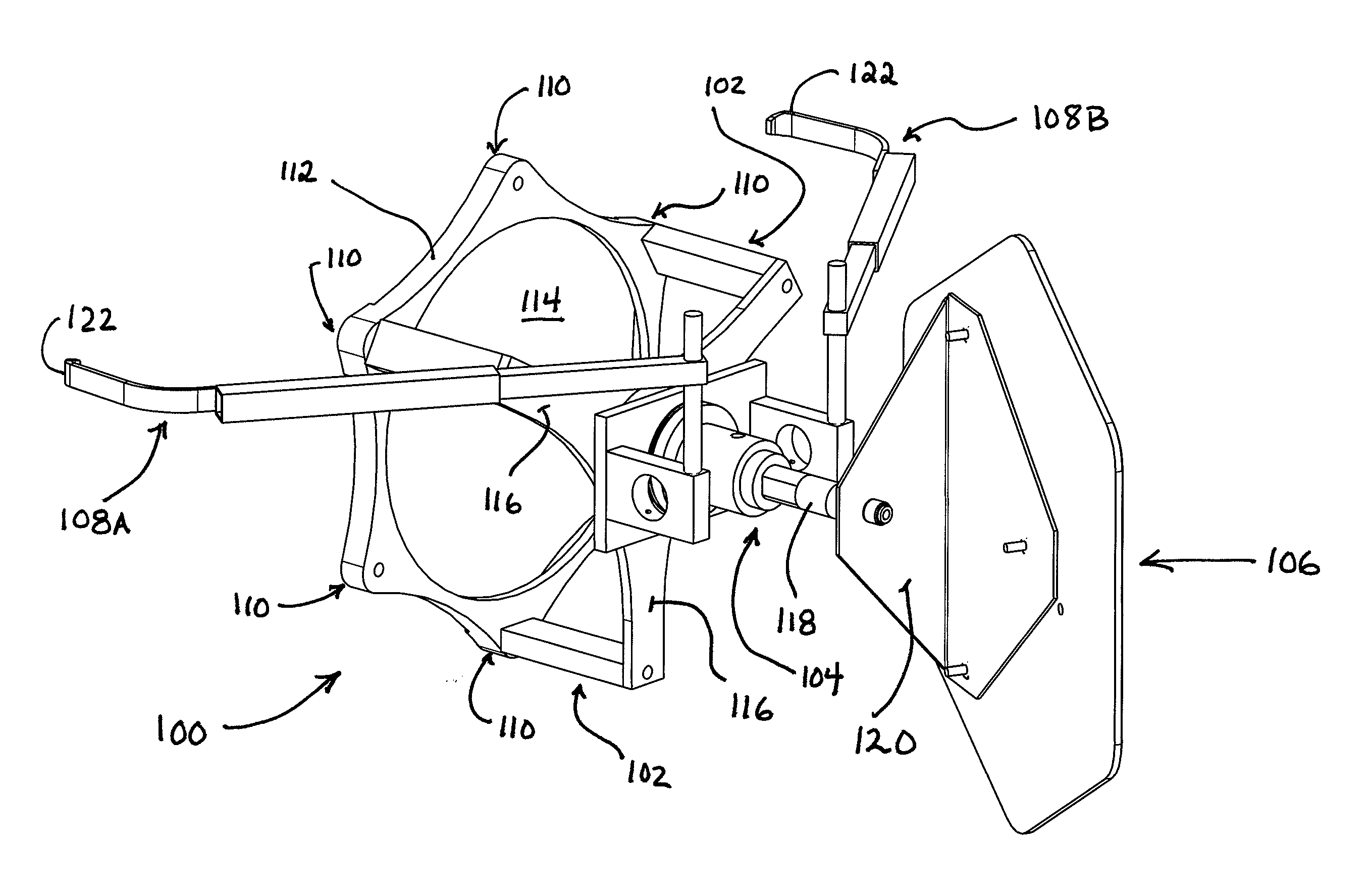
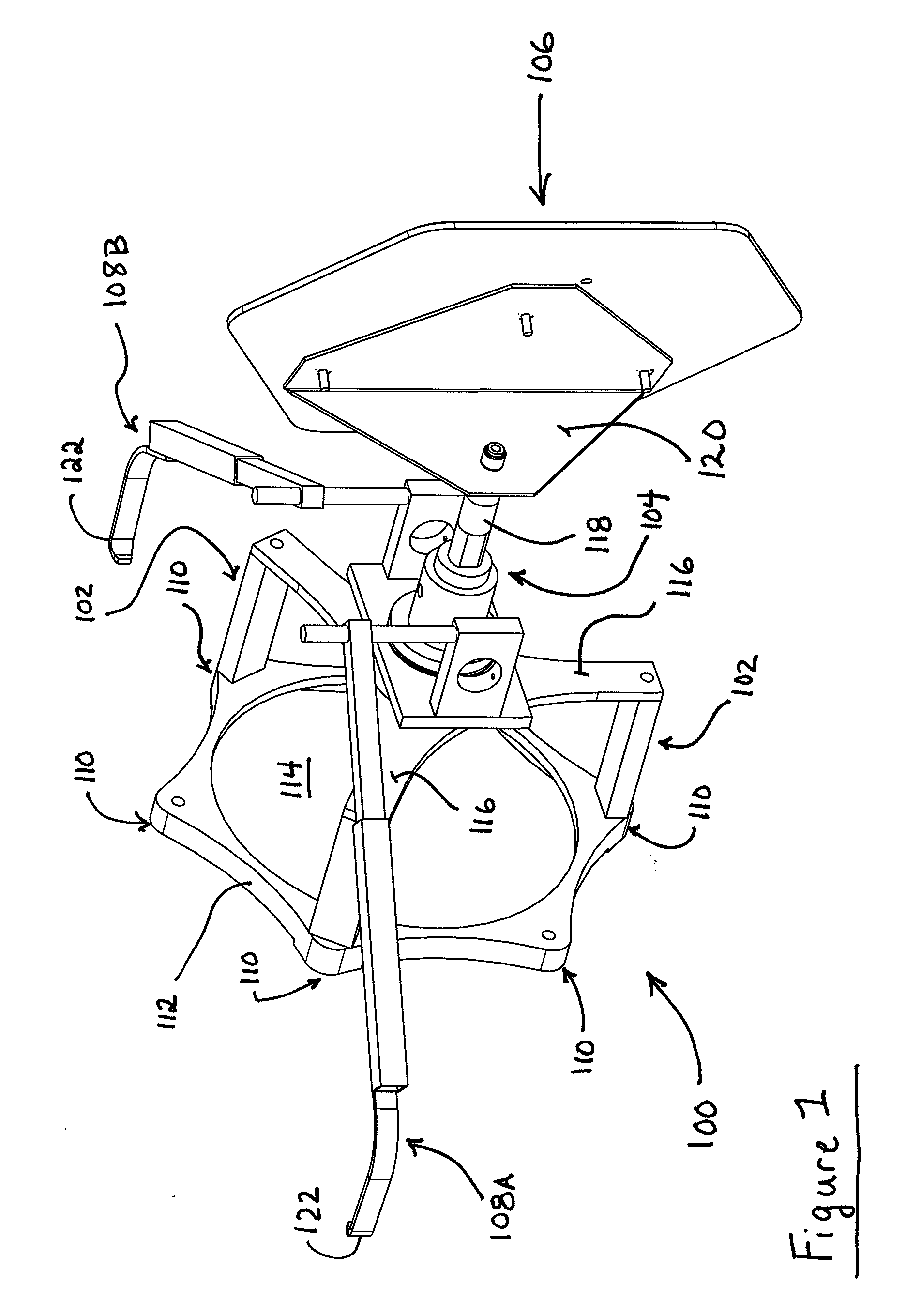
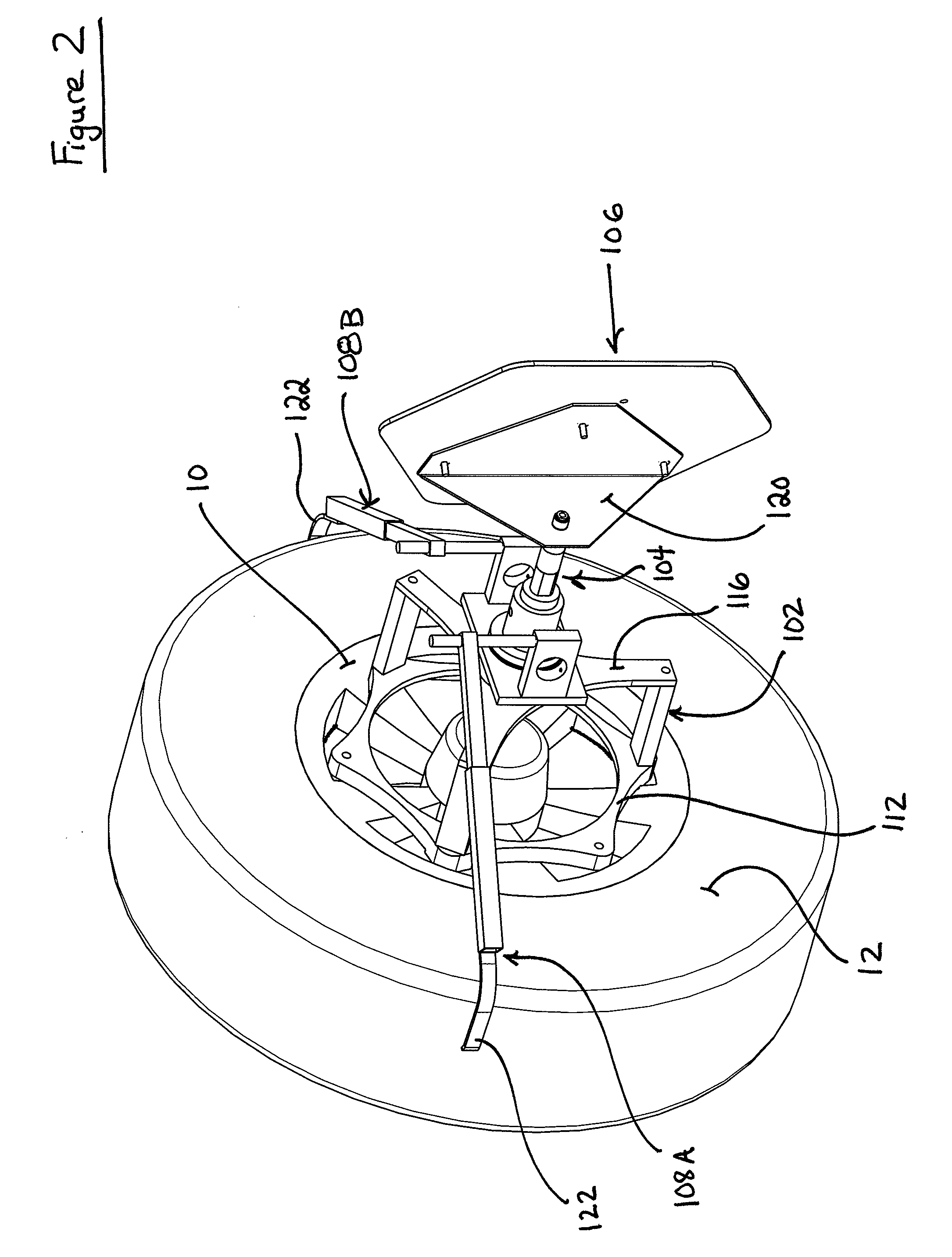
[0029] Turning to FIG. 1, an embodiment of the optical target assembly 100 of the present invention is shown in a rear perspective view. The optical target assembly 100 consists of a simplified or unitary base assembly 102, a pair of opposed wheel clamp arms 108A and 108B coupled to the base assembly, a target support assembly 104 coupled to the base assembly 102, and an optical target 106 secured to the target support assembly.

[0030] The simplified or unitary base assembly 102 defines one or more fixed contact surfaces 110 adapted for abutting contact with the generally vertical outer surfaces of a ve...


PUM


Abstract

A machine vision vehicle wheel alignment system optical target assembly incorporating an adaptor for attachment of an optical target to a vehicle wheel assembly. The adaptor includes at least three contact points for abutment against surfaces of a vehicle wheel assembly, and an attachment mechanism configured to grip surfaces of a tire mounted to the wheel rim to hold the optical target assembly in contact with the wheel assembly surface. The optical target is secured to the adaptor, and maintained in a fixed relationship to the wheel assembly thereby during a vehicle wheel alignment measurement procedure.

Description

CROSS-REFERENCE TO RELATED APPLICATIONS [0001] The present application is related to, and claims priority from, U.S. Provisional Patent Application Ser. No. 60 / 721,206 filed on Sep. 28, 2005, which is herein incorporated by reference.STATEMENT REGARDING FEDERALLY SPONSORED RESEARCH [0002] Not Applicable. BACKGROUND OF THE INVENTION [0003] The present invention relates to machine vision vehicle service systems, and in particular to an optical target assembly configured for mounting to a surface of a vehicle, such as a vehicle wheel, during a machine-vision vehicle wheel alignment procedure. [0004] A machine-vision vehicle service system, such as a vehicle wheel alignment system like the Series 811 Wheel Alignment System utilizing the DSP 600 Series sensors, manufactured and sold by Hunter Engineering Company of Bridgeton, Mo., consists generally of a console having a computer or processing unit, one or more display devices such as a monitor, and one or more input devices such as a ke...

Claims


Application Information

Patent Timeline
IPC IPC(8): G01B5/24
CPCG01B11/2755G01B2210/14G01B2210/30H04N7/18B60R11/04G01B2210/12G01B11/275
Inventor STIEFF, MICHAEL T.MEYER, GREGORY F.GOLAB, THOMAS J.DORRANCE, DANIEL R.SHYLANSKI, MARK S.
Owner HUNTER ENG
Why Eureka
Try Eureka