
Mole trapping system, mole trap and trap-setting assistance device, and methods of constructing and utilizing same

a technology of mole traps and traps, which is applied in the field of mole traps and mole traps, can solve the problems of many ineffective methods used in an attempt to get rid of moles, ineffective methods of getting rid of moles, and turning a lawn into rice paddy

Inactive Publication Date: 2007-03-29
BROWN ELGIN GLEN JR
View PDF99 Cites 12 Cited by
  • Summary
  • Abstract
  • Description
  • Claims
  • Application Information

AI Technical Summary

Benefits of technology

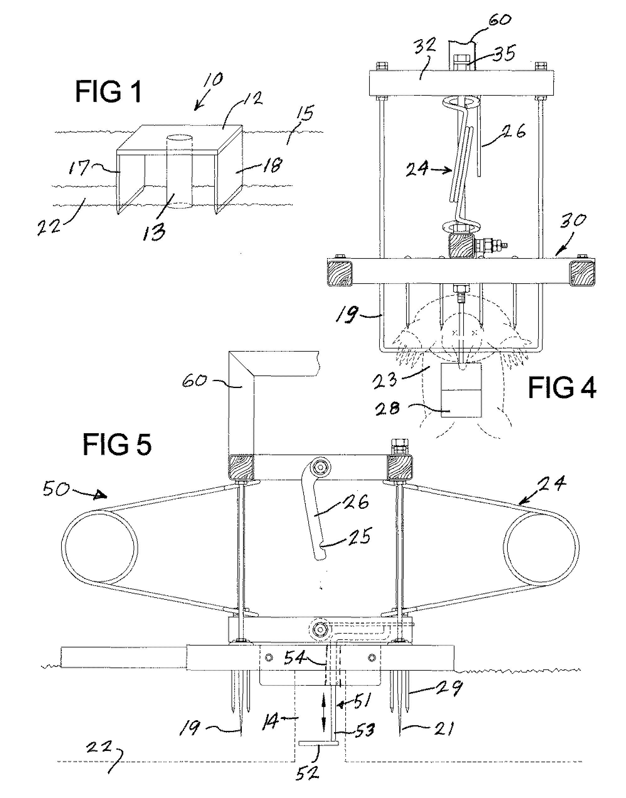
[0012] The present invention also provides device for facilitating a mole trap process and for facilitating setting of the mole trap, wherein said device comprises: a main horizontal platform member from which depends a central hole-cutting member for cutting a substantially vertical hole in the ground into which at least a portion of said trigger mechanism may be disposed; and two depending outer members for cutting slots in the ground to accommodate said U-shaped members.
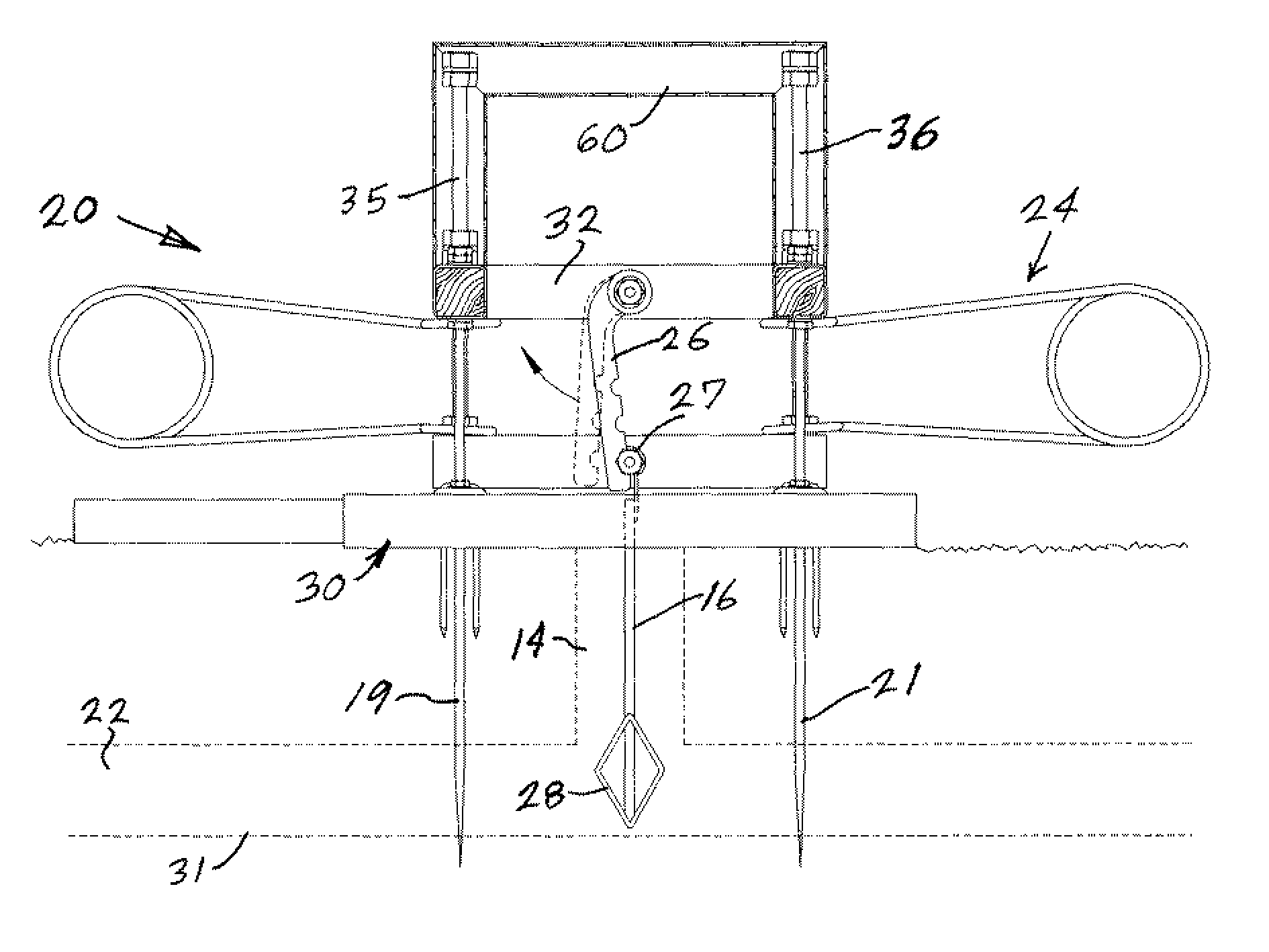
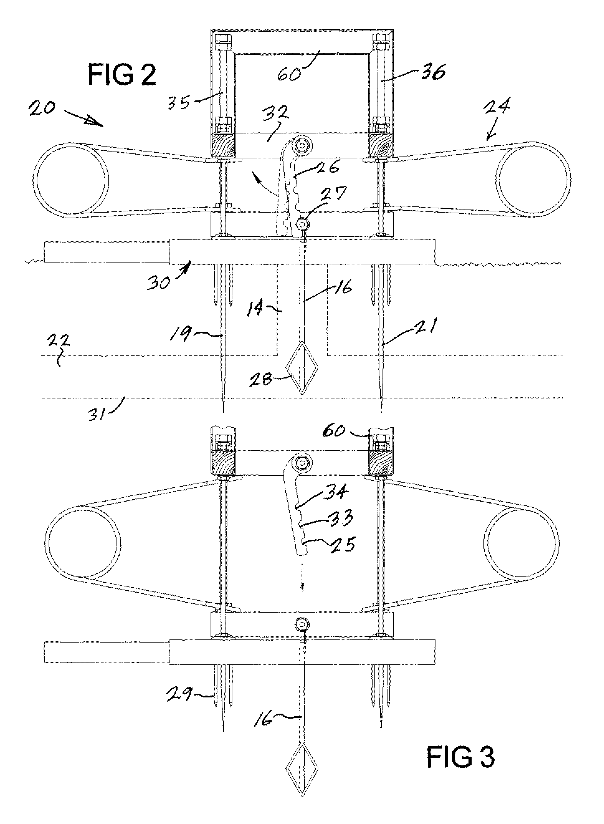
[0016] Yet a further object of the present invention is to provide a mole trap as described hereinabove, wherein the mole trap has a central trigger mechanism which is placed in a vertical hole communicating with the mole tunnel, and which fires very rapidly and kills the mole very quickly.
[0018] A further object of the present invention is to provide a mole trap as described hereinabove, wherein in one embodiment the mole can be traveling in either direction in the mole tunnel and the mole trap will trigger perfectly.

Problems solved by technology

Many ineffective methods have been used in an attempt to get rid of moles.
For example, one such ineffective method is running a hose into a mole tunnel, which invariably results in turning a lawn into a rice paddy.
Another ineffective method to get rid of moles is by gassing them with fumes from an automobile exhaust pipe.

Method used


Image

  • Mole trapping system, mole trap and trap-setting assistance device, and methods of constructing and utilizing same
  • Mole trapping system, mole trap and trap-setting assistance device, and methods of constructing and utilizing same
  • Mole trapping system, mole trap and trap-setting assistance device, and methods of constructing and utilizing same

Examples


Embodiment Construction

[0026] With reference to FIG. 1, there is shown a device 10 for facilitating starting the mole trap process and for facilitating setting of the mole trap 20 or 50.

[0027] The device 10 has a main horizontal platform 12 from which depends a central cylindrical hole-cutting member 13 for cutting a hole 14 in the ground 15 into which the trigger 16 or 51 of the mole trap 20 or 50, respectively, may be disposed, and two depending outer members 17 and 18 for cutting slots in the earth to accommodate the U-shaped members 19 and 21 of the mole trap 20 or 50.

[0028] The user would first see the track 22 of the mole 23 in the surface of the ground 15, and then position the cylindrical hole-cutting member 13 over the mole track or tunnel 22, and press the device 10 downwardly into the ground 15. This cuts a vertical cylindrical hole 14 into the mole track 22, and at the same time provides two outer slots in the ground 15 to accommodate the U-shaped members 19 and 21 of the mole trap 20 or 50....


PUM


Abstract

A mole trap having a bottom frame with spikes beneath it above a mole tunnel. A top frame is slidably connected to the bottom frame. A spring mechanism is positioned between the top and bottom frames. Two U-shaped members are placed in the ground extending beneath the mole tunnel. A movable trigger mechanism extends in the vicinity of the mole tunnel. The trigger mechanism is instantly tripped when a mole or earth moved by the mole touches a portion of the trigger mechanism, and thrusts the two U-shaped members upwardly with the mole to impale the mole on spikes.

Description

CROSS-REFERENCE TO RELATED APPLICATIONS [0001] The present application is a continuation-in-part of and claims priority from U.S. Provisional Patent Application Ser. No. 60 / 596,490 filed Sep. 28, 2005.STATEMENT REGARDING FEDERALLY SPONSORED RESEARCH OR DEVELOPMENT [0002] Not Applicable REFERENCE TO SEQUENCE LISTING, A TABLE, OR A COMPUTER PROGRAM LISTING COMPACT DISC APPENDIX [0003] Not Applicable. BACKGROUND OF THE INVENTION [0004] The present invention relates to a mole trapping system, a mole trap and a trap-setting assistance device, and methods of constructing and utilizing same. [0005] More particularly, the present invention relates to a mole trapping system and a mole trap having a substantially horizontally-arranged spring mechanism which thrusts two U-shaped members upwardly carrying the mole to impale the mole on a plurality of spikes. [0006] Many ineffective methods have been used in an attempt to get rid of moles. For example, one such ineffective method is running a ho...

Claims


Application Information

Patent Timeline
IPC IPC(8): A01M23/36
CPCA01M27/00A01M23/36
Inventor BROWN, ELGIN GLEN JR.
Owner BROWN ELGIN GLEN JR
Learn More