
Kiln door

a kiln and door technology, applied in the field of kiln doors, can solve the problems of easy damage, difficult or costly replacement and/or repair, weakest and most troublesome parts of the kiln structure, etc., and achieve the effect of improving sealing ability, easy shipping and assembly

Inactive Publication Date: 2007-03-29
THE COE MANUFACTORING
View PDF10 Cites 6 Cited by
  • Summary
  • Abstract
  • Description
  • Claims
  • Application Information

AI Technical Summary

Benefits of technology

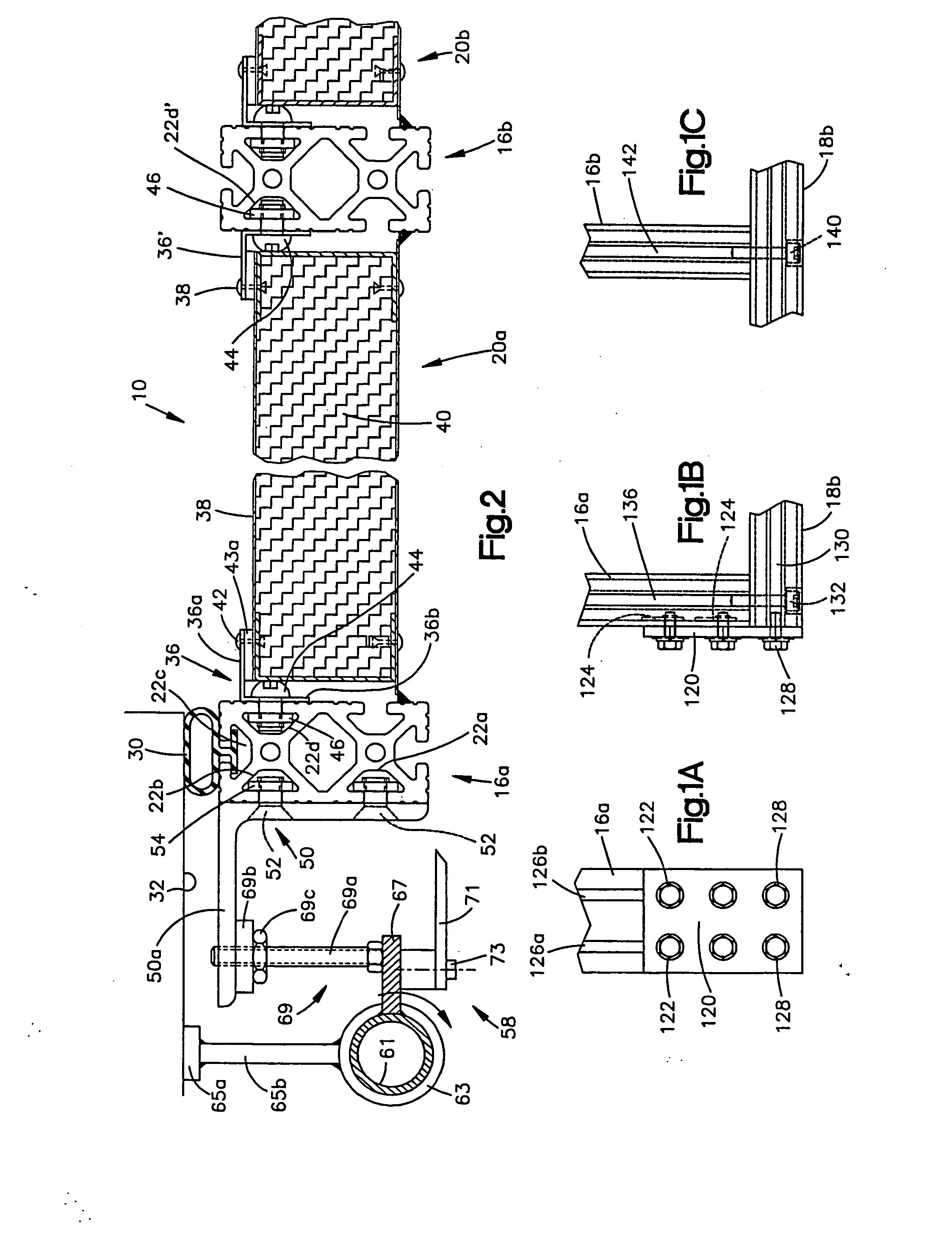
"The present invention provides a new and improved kiln door that can easily replace existing kiln doors. The disclosed door has improved sealing capability and can be easily shipped and assembled at a job site. The door assembly includes a door frame formed by prefabricated vertical frame members interconnected with prefabricated lateral frame members. Insulated panel sections are replaceably supported by the door frame. The lateral and vertical frame members each include a plurality of T-slots for holding threaded members engagable with threaded fasteners to hold the panel sections to the door frame. The door assembly also includes a clamp pressure receiving structure for receiving clamping pressure exerted by a clamp mechanism that forms part of the kiln structure. The clamping mechanism applies a predetermined clamping pressure to the door assembly in order to provide a sealing engagement between at least a portion of the peripheral door seals and the door opening in the kiln. The door assembly also includes at least one roller that extends outwardly and is engagable by another, passing door assembly."

Problems solved by technology

The doors are frequently the weakest and most troublesome part of the kiln structure.
They can be easily damaged when they are opened or closed carelessly or by an inattentive operator who damages the door with lumber handling equipment.
It has been found that in many current kiln structures, the doors are susceptible to damage and are very difficult or costly to replace and / or repair.

Method used


Image

  • Kiln door
  • Kiln door
  • Kiln door

Examples


Embodiment Construction

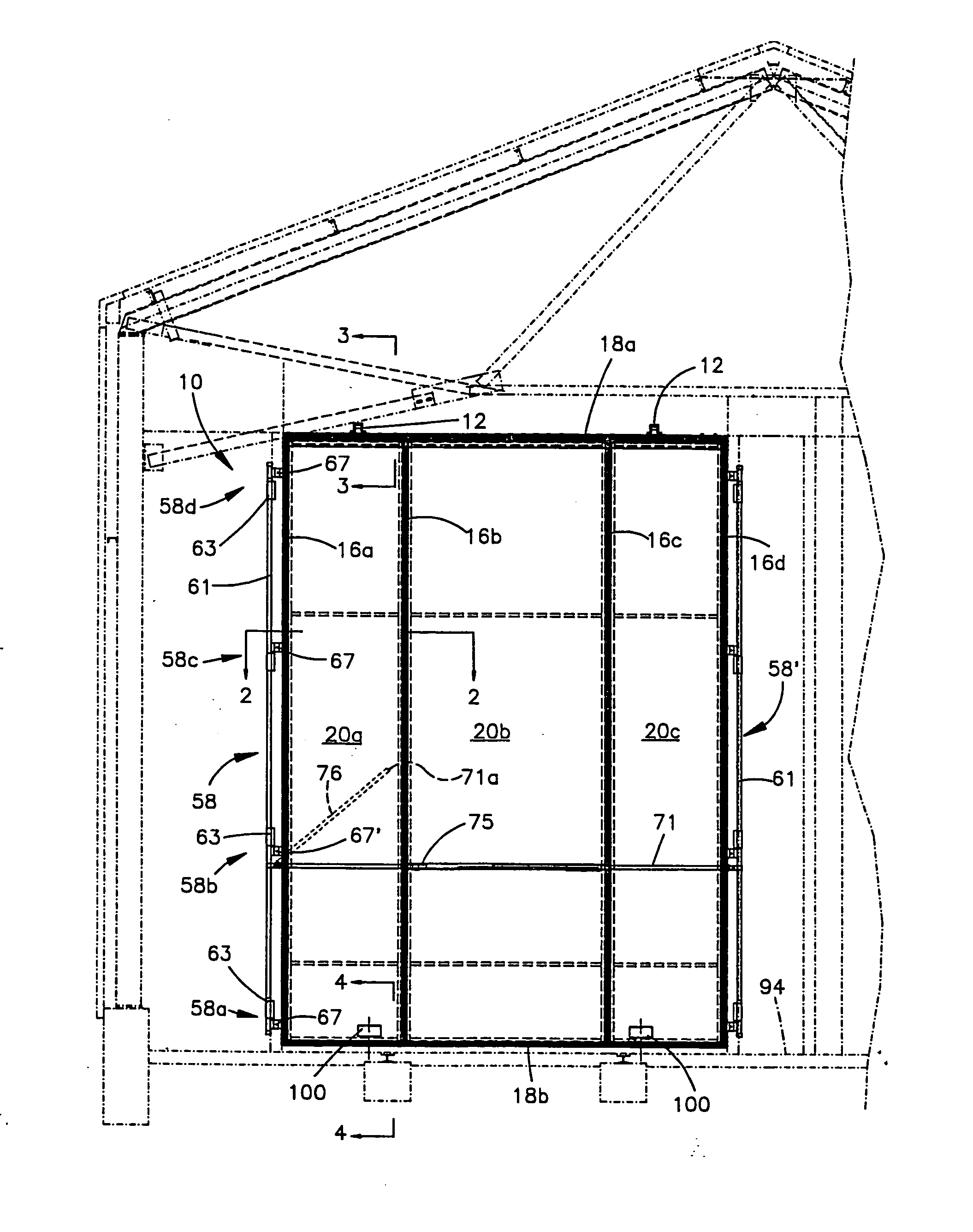
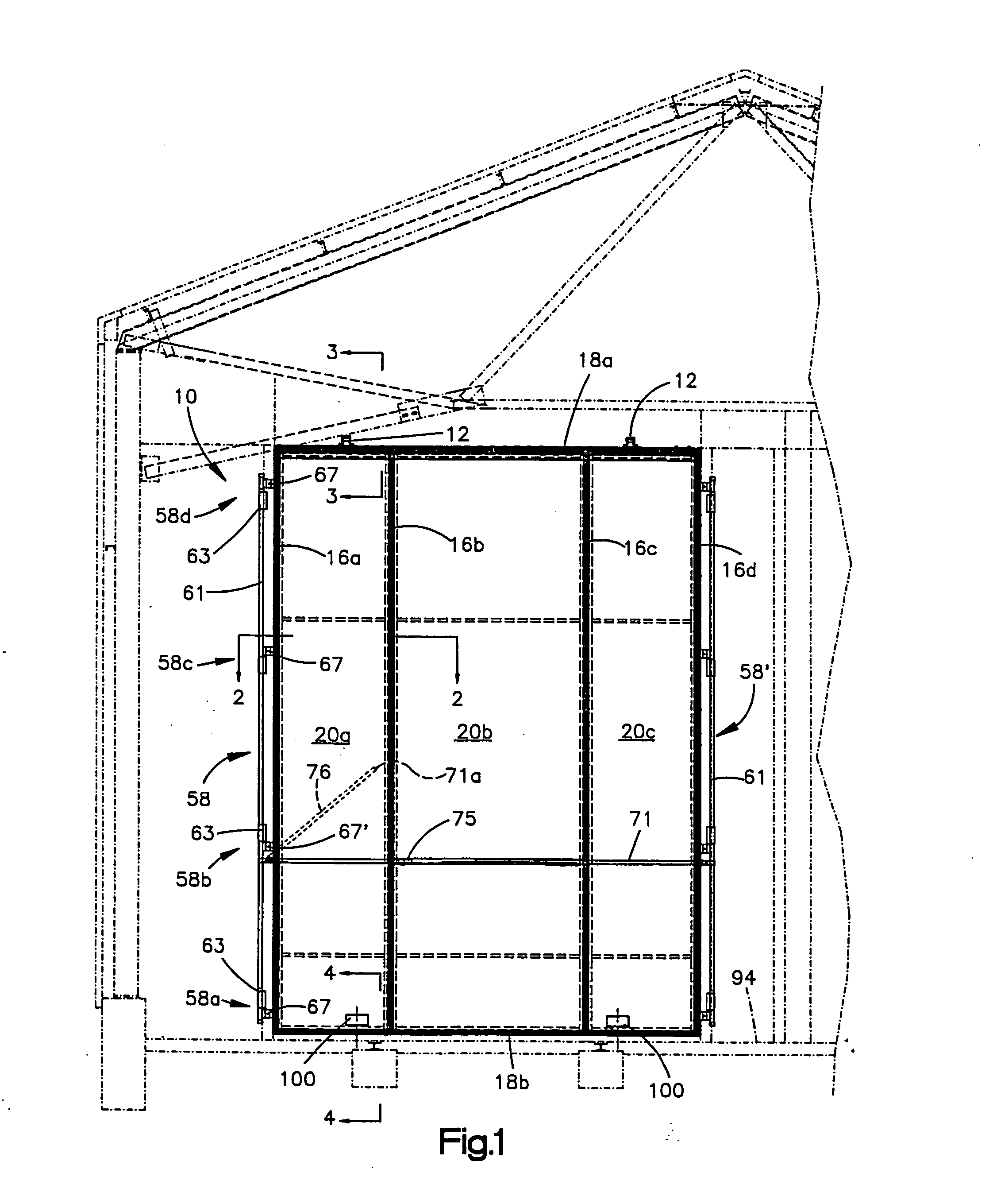
[0016]FIG. 1 illustrates the overall construction of a kiln door 10 constructed in accordance with the preferred embodiment of the invention. In the illustrated embodiment, the door 10 is of the type that is hung from hooks 11 (one which is shown in FIG. 3) by a pair of hangers 12. The hooks 11 are attached to the door frame of the Kiln 14. A door carrier (not specifically shown) is used to raise the door 10 off the hooks and support it for lateral movement with respect to the door frame. The construction of the hangers 12 and the method by which they interact with the door carrier is conventional. In operation, a mechanism forming part of the door carrier (not shown) raises the door slightly and due to the engagement between the hangers 12, the hooks 11 and the door carrier, the door 10 moves upwardly and outwardly from the door opening defined by the kiln structure 14, a portion of which is shown in phantom. As is also conventional, once the door 10 is raised and moved outwardly, ...


PUM


Abstract

A door assembly for a kiln that includes a door frame formed by prefabricated vertical frame members that are interconnected with prefabricated lateral frame members. Insulated panel sections are replaceably supported by the door frame. Replaceable, peripheral door seals are held in track ways. The track ways are defined by the vertical and lateral frame members. Each lateral and vertical frame member includes a plurality of T-slots for receiving threaded members that are engagable with threaded fasteners used to hold the panel sections to the door frame. The door assembly includes clamp pressure receiving structure for receiving a clamping pressure exerted by a clamp mechanism forming part of the kiln structure whereby a sealing engagement is provided between a peripheral seal on the door frame. A roller extending outwardly from the door assembly is engagable by another, passing door assembly.

Description

CROSS-REFERENCE TO RELATED APPLICATION [0001] This application claims priority from Provisional Application Ser. No. 60 / 709,834 filed on Aug. 19, 2005. Provisional Application No. 60 / 790,834 is incorporated in its entirety herein by reference.TECHNICAL FIELD [0002] The present invention relates generally to processing lumber in a kiln and in particular, to a new and improved kiln door. BACKGROUND ART [0003] Kilns are often used in the lumber industry to adjust the moisture content of lumber. Generally, a kiln is a rather large structure that defines one or more chambers in which the lumber is placed. When the lumber is being processed, it is important to seal the interior of the kiln from the outside atmosphere so that the environment within the drying chamber is controlled. It is also important that the heated air within the chamber be inhibited from leaking out of the chamber i.e., through door interfaces, etc. [0004] Kilns typically have rather large access doors that are moved l...

Claims


Application Information

Patent Timeline
Patent Type & Authority Applications(United States)
IPC IPC(8): E06B1/04
CPCE06B3/08E06B3/12E06B3/76E06B2003/7074E06B2003/7011E06B2003/7046E06B5/14
Inventor MIERAU, CAMERON DEANCALEEN, LAWRENCE PATRICKBENSEN, BRUCE SCOTT
Owner THE COE MANUFACTORING
Learn More