Backhoe

Inactive Publication Date: 2007-03-29
KUBOTA LTD
View PDF9 Cites 15 Cited by
  • Summary
  • Abstract
  • Description
  • Claims
  • Application Information

AI Technical Summary

Benefits of technology

[0019] This construction allows the two longitudinal ribs to reinforce each other, and distribute stress between each other.
[0020] According to this invention, an improvement is realized in mutual assembly strength

Problems solved by technology

The right and left longitudinal ribs are not connected to each othe

Method used


Image

  • Backhoe
  • Backhoe
  • Backhoe

Examples


Example

[0035] An embodiment of this invention will be described hereinafter with reference to the drawings.

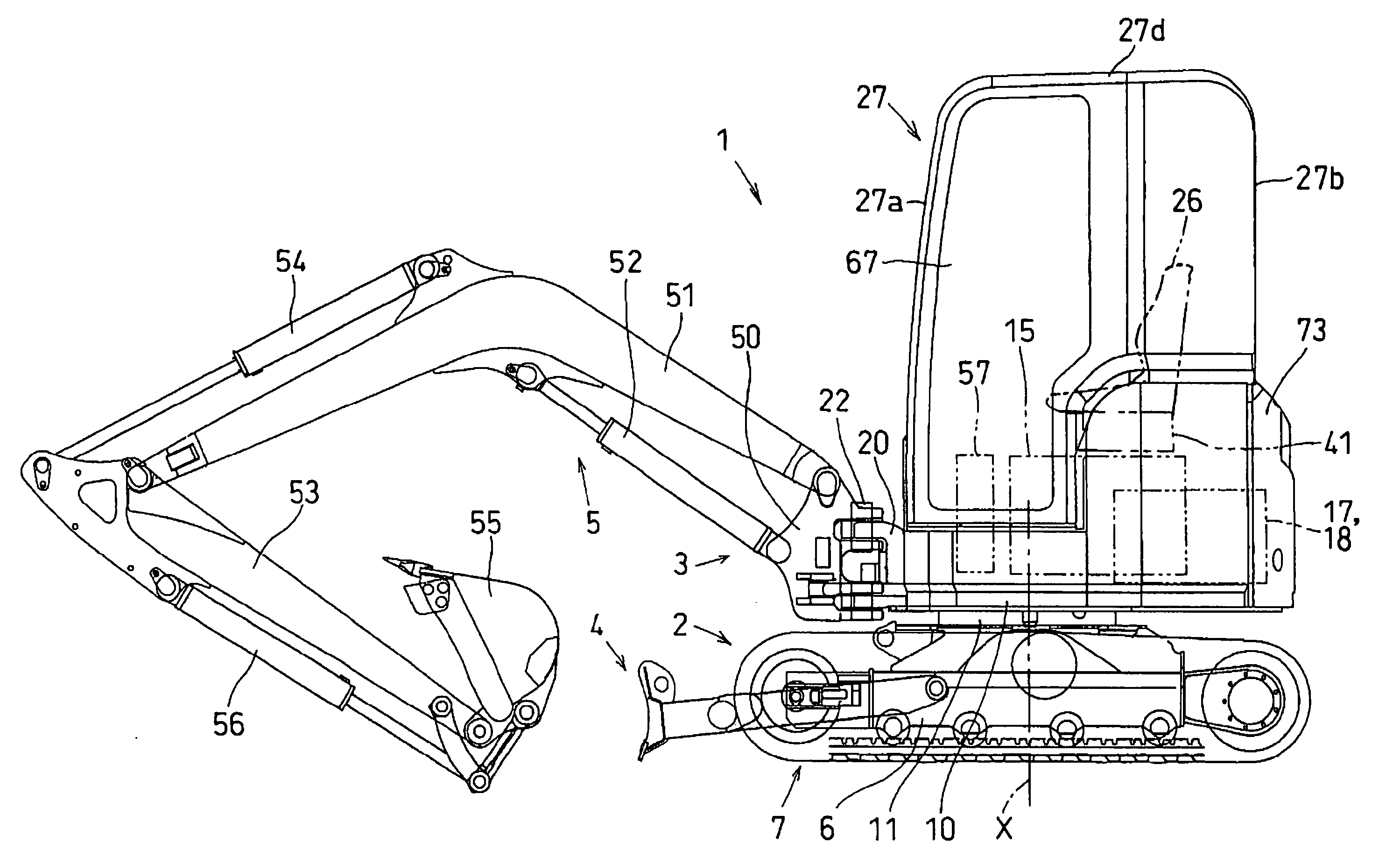
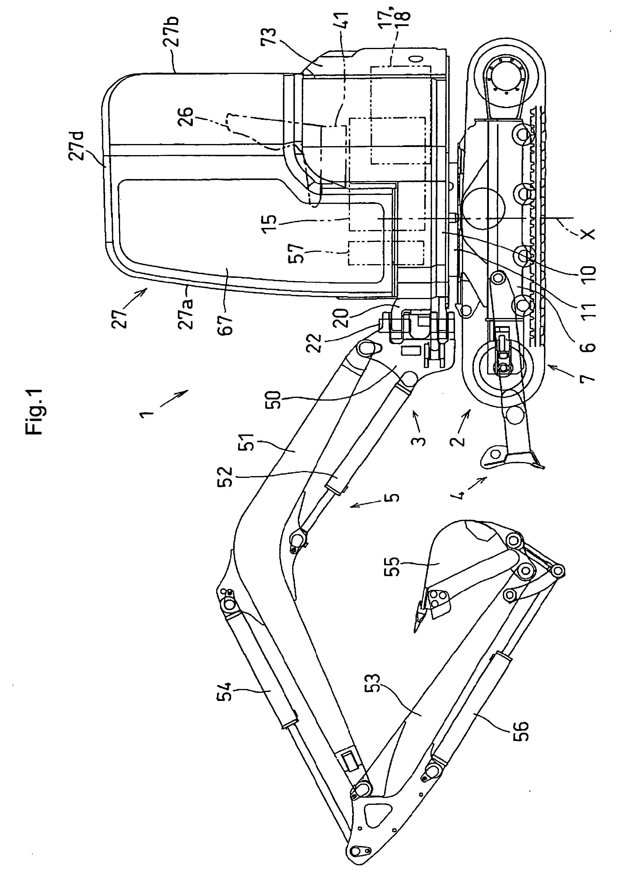
[0036] In FIGS. 1-14, a backhoe 1 of the rear small revolution type (swivel type working vehicle), includes a traveling device 2 disposed below, an upper structure 3 disposed above, a dozer apparatus 4 attached to the front of the traveling device 2, and a ground working implement 5 attached to the upper structure 3.

[0037] The traveling device 2 has crawler traveling means 7 arranged at right and left side of a track frame 6 to be driven by hydraulic motors. The track frame 6 supports thereon a swivel deck 10 which is a base of the upper structure 3, to be swivelable through a swivel bearing 11 about a swivel center (vertical axis) X. The swivel deck 10 is driven by a swivel motor 8 mounted thereon. The dozer apparatus 4 has a blade vertically movable in front of the track frame 6.

[0038] The track frame 6 has a swivel joint 12 disposed centrally of the swivel bearing 11. The swivel...


PUM


Abstract

An improvement is realized in mutual assembly strength between a swing bearing member and right and left longitudinal ribs, and welds are subjected to a reduced stress concentration. A backhoe comprises a swivel deck (10); a first longitudinal rib (19L) disposed on the swivel deck, the first longitudinal rib extending in a fore and aft direction, and having a front portion (19La) extending in a transverse direction; a second longitudinal rib (19R) disposed on said swivel deck, the second longitudinal rib extending in the fore and aft direction, and having a front end thereof connected to the front portion of the first longitudinal rib; and a swing bearing member (20) attached to a front surface of the front portion of the first longitudinal rib for supporting a ground working implement through a swing shaft.

Description

BACKGROUND OF THE INVENTION [0001] 1. Field of The Invention [0002] This invention relates to a backhoe having a ground working implement connected to the front of a swivel deck. [0003] 2. Description of the Related Art [0004] In this type of conventional technique, a support frame bifurcated in plan view has a right and left longitudinal ribs and a front swing bearing member on the swivel slide. The swing bearing member of the support frame supports the ground working implement through a swing shaft. A hydraulic oil tank and a fuel tank are arranged at the right-hand side on the swivel slide, and a swing cylinder for swinging the ground working implement is disposed below these tanks. An engine and a counter weight are arranged on a rear portion of the swivel deck (see Japanese Unexamined Patent Publication No. 2005-232795, for example). [0005] In the above conventional technique, the forward ends of the right and left longitudinal ribs are welded to right and left rear positions o...

Claims


Application Information

Patent Timeline
IPC IPC(8): B62D33/08
CPCE02F9/0808E02F3/384
Inventor MIYAKE, TOMOAKI
Owner KUBOTA LTD
Why Eureka
Try Eureka