
Surgical stapling instrument having preloaded firing assistance mechanism

a technology of preloaded firing and assistance mechanism, which is applied in the direction of surgical staples, surgical forceps, paper/cardboard containers, etc., can solve the problems of inconvenient or difficult for surgeons with limited hand strength, long and narrow instruments used in such procedures, etc., and achieve the effect of effective firing of the implement portion and reducing opposition to firing

Active Publication Date: 2007-03-29
CILAG GMBH INT
View PDF28 Cites 129 Cited by
  • Summary
  • Abstract
  • Description
  • Claims
  • Application Information

AI Technical Summary

Benefits of technology

[0011] In another aspect of the invention, a surgical instrument includes a proximal portion of a firing mechanism that is held in place by a brake of an engagement mechanism when a follower member is moved from a fired position to an unfired position, which preloads a biasing member in the opposite direction, and engages the biased follower member to the firing mechanism. Firing of the firing mechanism releases the brake to enable assisted firing. Thereby, an effective firing of the implement portion is achieved even if high firing forces are required and the surgeon has limited strength to move the firing mechanism to achieve the required firing forces.
[0012] In yet another aspect of the invention, a surgical instrument incorporates preloading of a retraction assistance mechanism that is disengaged during firing to reduce opposition to firing, yet readily engages after firing to retract the firing member through the elongate implement portion.

Problems solved by technology

Moreover, laparoscopic and endoscopic procedures often require the surgeon to act on organs, tissues and / or vessels far removed from the incision.
Thus, instruments used in such procedures are typically long and narrow while being functionally controllable from a proximal end of the instrument.
The requirement of a higher force to operate the trigger may be inconvenient or difficult for a surgeon with limited hand strength.

Method used


Image

  • Surgical stapling instrument having preloaded firing assistance mechanism
  • Surgical stapling instrument having preloaded firing assistance mechanism
  • Surgical stapling instrument having preloaded firing assistance mechanism

Examples


Embodiment Construction

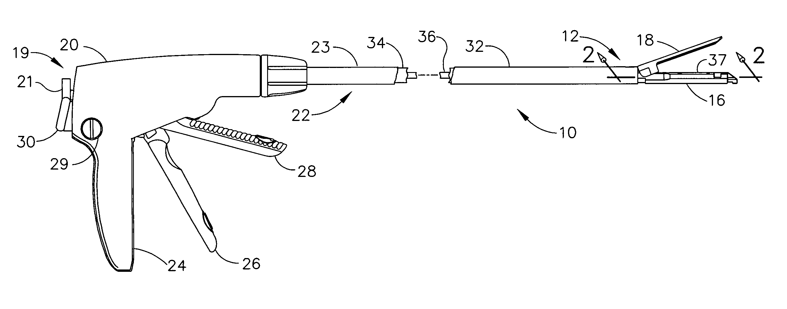
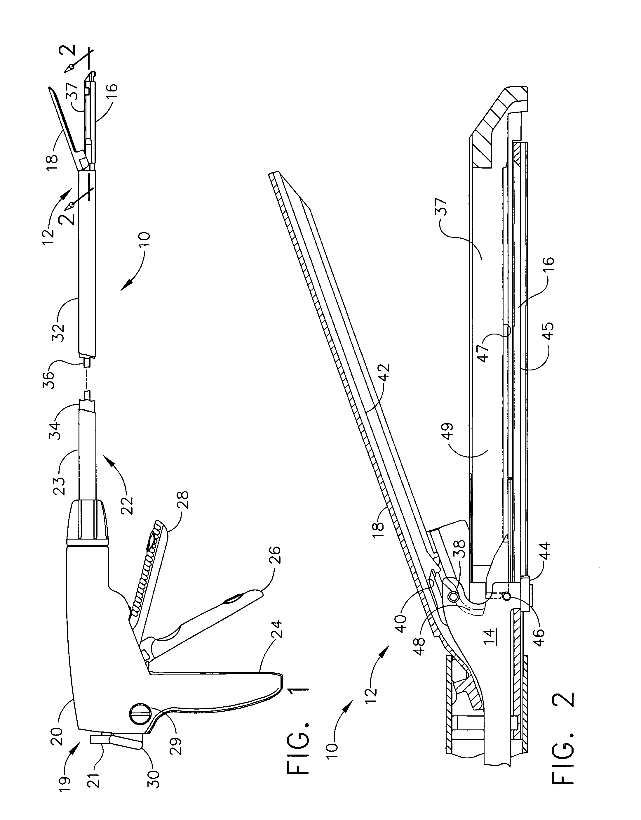
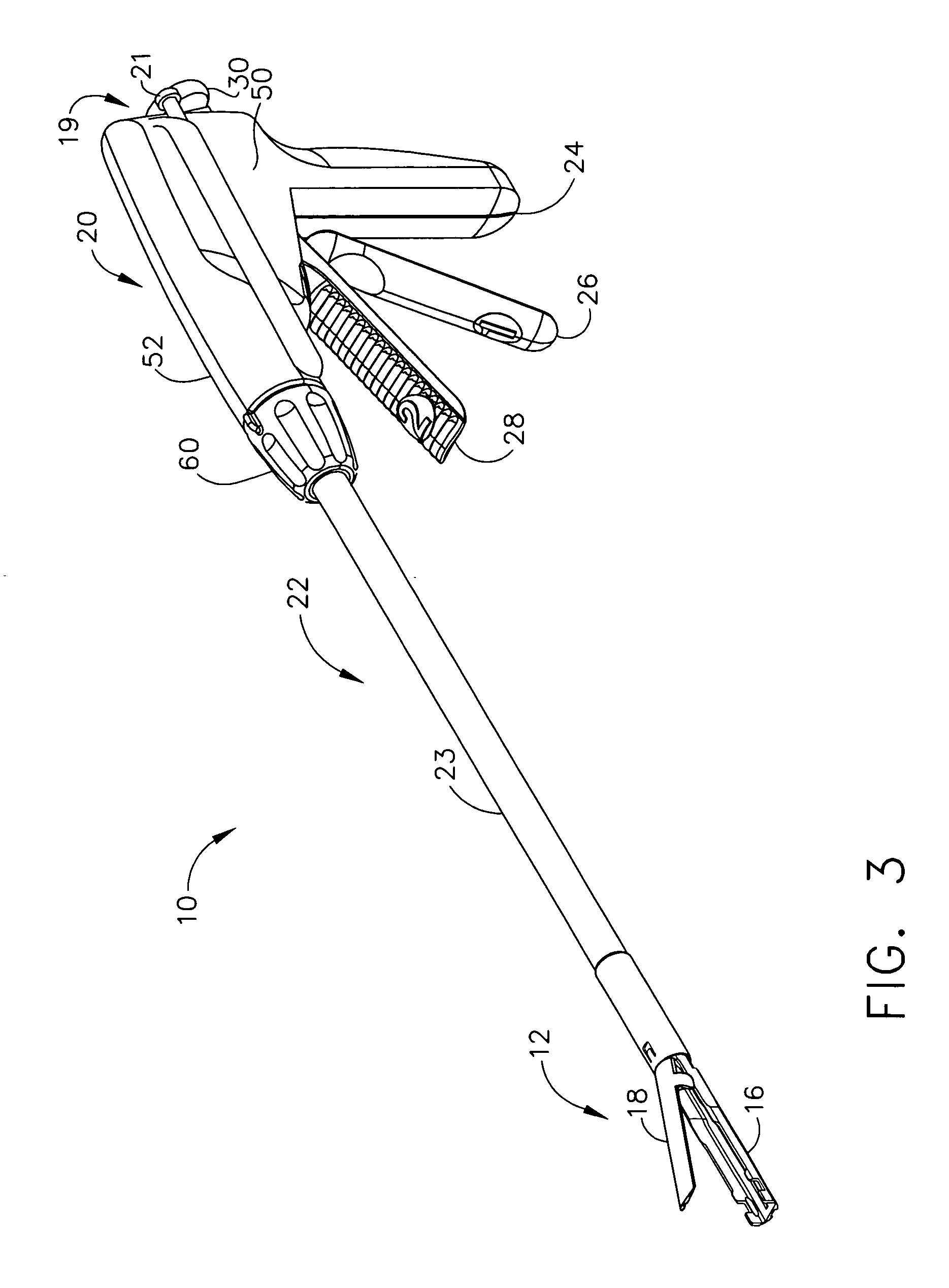
[0067] Turning to the Drawings, wherein like numerals denote like components throughout the several views, in FIG. 1, a surgical stapling and severing instrument 10 is depicted that is capable of practicing the unique benefits of the present invention. The surgical stapling and severing instrument 10 incorporates an end effector 12, which in the illustrative version is a staple applying assembly having an E-beam firing member (“firing bar”) 14 (FIG. 2) that controls the spacing of the end effector 12. In particular, an elongate channel 16 and a pivotally translatable anvil 18 are maintained at a spacing that assures effective stapling and severing. Firing this firing bar 14 requires an amount of force to sever tissue, form staples, and to overcome mechanical resistance in the surgical stapling and severing instrument 10. Consistent with aspects of the present invention, an assistance mechanism 19 is incorporated into a handle portion 20 to reduce the amount of force necessarily impa...


PUM

PropertyMeasurementUnit
angleaaaaaaaaaa
tensionaaaaaaaaaa
movementaaaaaaaaaa

Abstract

A surgical severing and stapling instrument clamps tissue in a staple applying assembly comprising a lower jaw of an elongate channel holding a staple cartridge and a pivotally opposed upper jaw (anvil). A firing handle drives a rack in a handle connected to a firing rod and bar that pass through an elongate shaft and into the staple applying assembly to sever and staple tissue. Upon release of the firing handle, a retraction spring assists in withdrawing the rack and other firing components. To advantageously assist in firing, a spring biased plunger is cocked prior to firing to impart assistance upon depression of the firing trigger. Alternatively, a torsion coil spring ratchet mechanism is preloaded to act through a gear into the rack to assist. As a further alternative, a retraction spring is preloaded and disengaged until the rack is fully fired.

Description

FIELD OF THE INVENTION [0001] The present invention relates in general to surgical stapler instruments that are capable of applying lines of staples to tissue while cutting the tissue between those staple lines and, more particularly, to improvements relating to stapler instruments and improvements in processes for forming various components of such stapler instruments. BACKGROUND OF THE INVENTION [0002] Endoscopic and laparoscopic surgical instruments are often preferred over traditional open surgical devices since a smaller incision tends to reduce the post-operative recovery time and complications. The use of laparoscopic and endoscopic surgical procedures has been relatively popular and has provided additional incentive to develop the procedures further. In laparoscopic procedures, surgery is performed in the interior of the abdomen through a small incision. Similarly, in endoscopic procedures, surgery is performed in any hollow viscus of the body through narrow endoscopic tubes...

Claims


Application Information

Patent Timeline
Patent Type & Authority Applications(United States)
IPC IPC(8): A61B17/10
CPCA61B17/07207A61B2017/320052A61B2017/2923A61B2017/00398
Inventor SHELTON, FREDERICK E. IVSWAYZE, JEFFREY S.TIMPERMAN, EUGENE L.FUGIKAWA, LESLIE M.
Owner CILAG GMBH INT
Learn More