Tube-style truck body

a truck body and tube-style technology, applied in the direction of transportation and packaging, loading/unloading vehicle arrangment, transportation items, etc., can solve the problems of inconsistency in shape, increased time required to manufacture the truck body, and not being able to withstand bending and twisting

a truck body and tube-style technology, applied in the direction of transportation and packaging, loading/unloading vehicle arrangment, transportation items, etc., can solve the problems of inconsistency in shape, increased time required to manufacture the truck body, and not being able to withstand bending and twisting

US20070069569A1Active Publication Date: 2007-03-29THINK RITE INTPROP LLC

Image

  • Tube-style truck body
  • Tube-style truck body
  • Tube-style truck body

Examples


Embodiment Construction

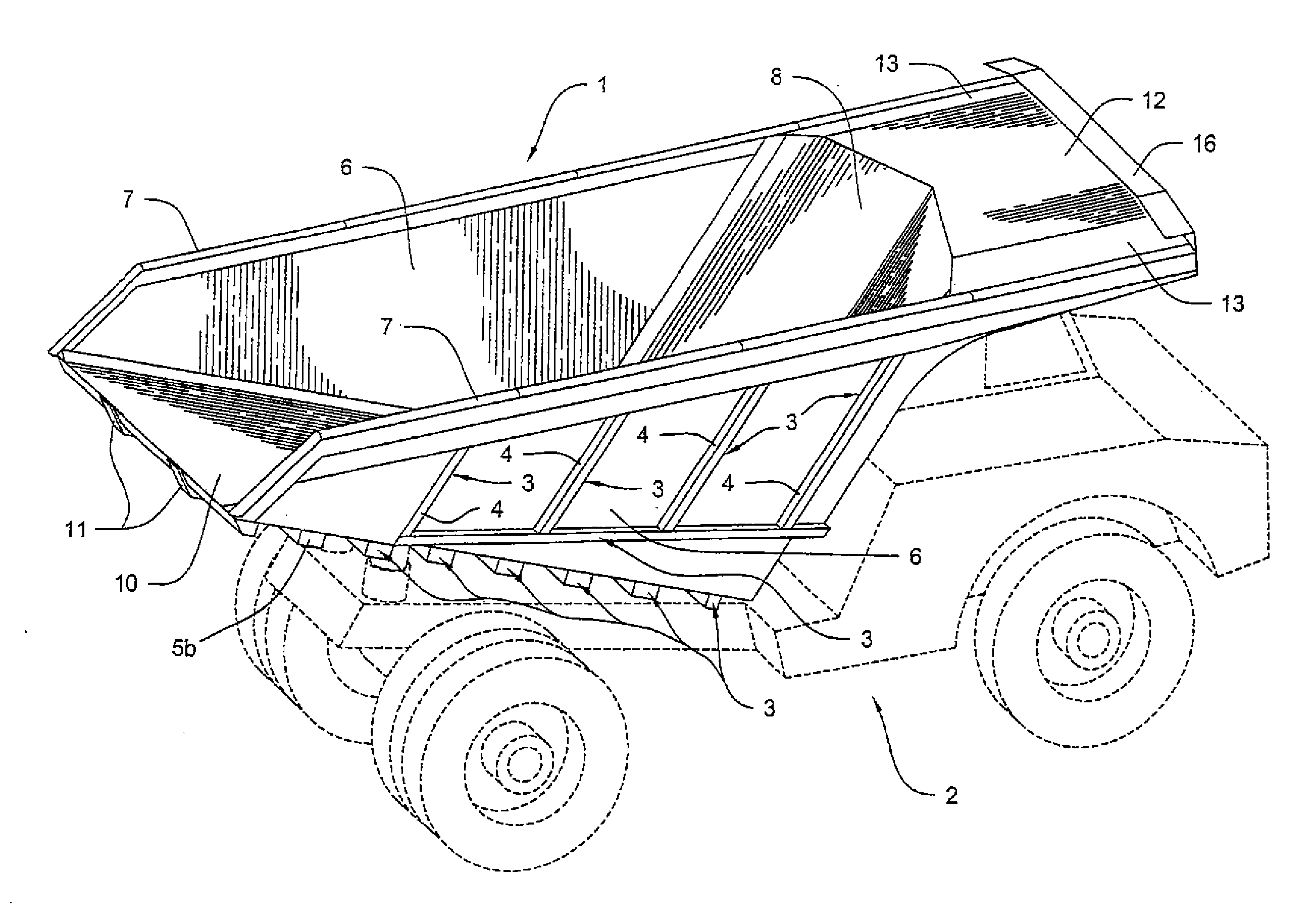
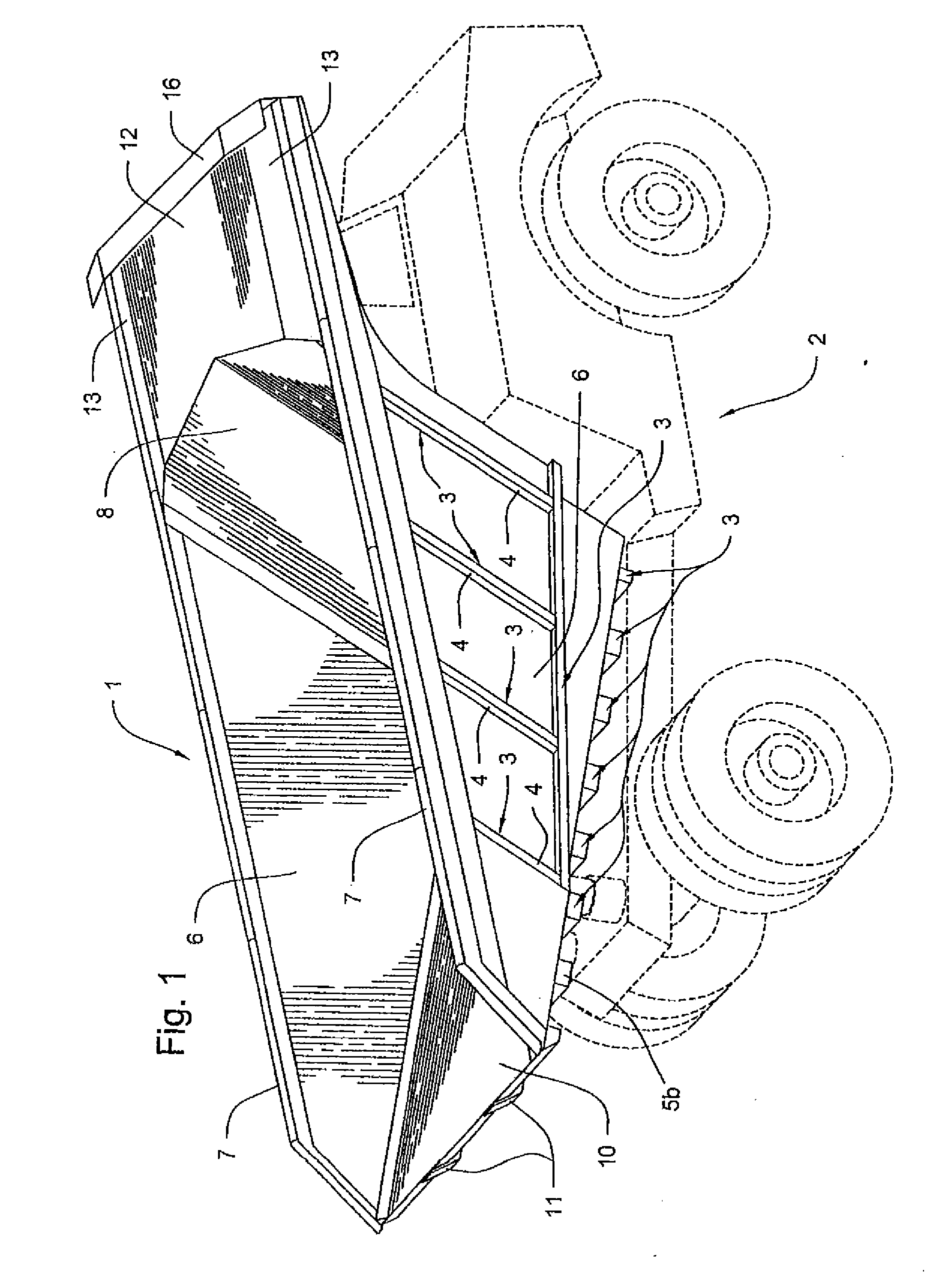
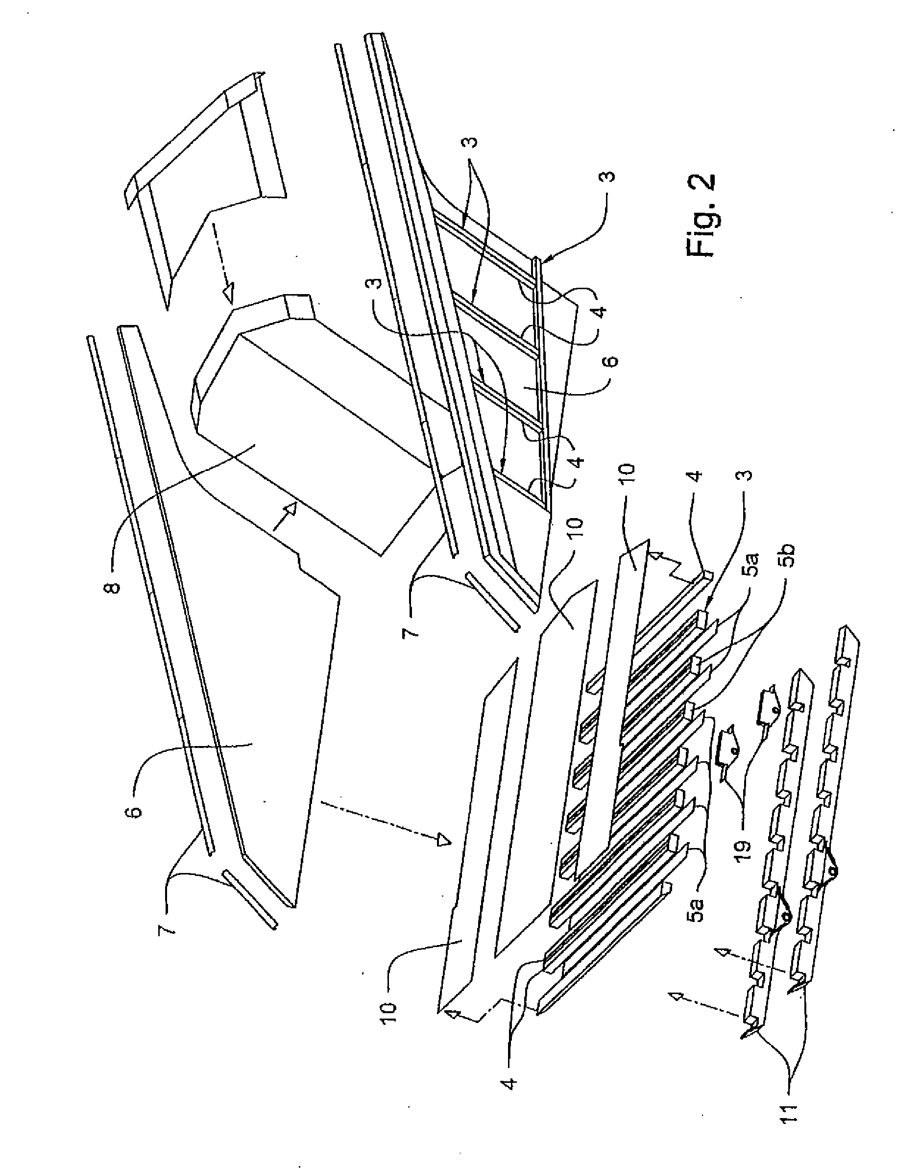
[0063]FIG. 1 is a perspective view of the truck body of the present invention installed on a chassis. This figure shows the truck body 1 and the chassis 2. The truck body 1 comprises a plurality of tube-style support members 3. Each tube-style support member 3 is comprised of one or two pieces of square tubing 4. The former is referred to as a single-size tube-style support member, and the latter is referred to as a double-size tube-style support member. If two pieces of square tubing 4 are used to form one tube-style support member 3, then a cover plate 5a (shown in FIG. 2) is welded onto the top of both pieces of square tubing 4 to give them the strength and appearance of a single structure.

[0064] The number and configuration (i.e., combination of single- and double-size tube-style support members) will vary depending on the size and strength requirement of the truck body based on the particular application involved. The present invention is not limited to any particular number o...


PUM


Abstract

An off-highway truck body comprising a plurality of tube-style support members, wherein each tube-style support member comprises one or two pieces of square tubing, wherein the truck body comprises two sidewalls, a floor, a front wall and a canopy, and wherein one side of each tube-style support member is welded to the outside of the sidewall, floor, front wall or canopy. The pieces of square tubing are preferably comprised of steel. The present invention optionally comprises a forward wedged front wall and a side-sloped canopy. The present invention also encompasses a tube-style tailgate and an alternate embodiment in which I-beams are used in lieu of square tubing.

Description

CROSS-REFERENCE TO RELATED APPLICATION [0001] This application is a continuation-in-part of U.S. patent application Ser. No. 11 / 214,129, filed on Aug. 29, 2005.BACKGROUND OF THE INVENTION [0002] 1. Field of the Invention [0003] The present invention relates to the field of off-highway truck bodies, and more particularly, to a tube-style truck body with a forward wedged front wall and side-sloped canopy. [0004] 2. Description of the Related Art [0005] A traditionally built off-highway truck body is comprised of a plurality of bent steel ribs that form the skeletal structure or framework of the truck body, and solid steel plates overlying the ribs to form the truck box or container in which the material is held. The steel ribs are formed by bending flat sheets of steel and then welding them to the steel plates that form the truck box. These ribs are typically shaped like a ā€œUā€ or a ā€œVā€ with the open side of the ā€œUā€ or ā€œVā€ facing inward (attached to the steel plates). [0006] The proble...

Claims


Application Information

Patent Timeline
29 Mar 2007
Publication
US20070069569A1
IPC
B65G67/24; B60R99/00
CPC
B62D33/02; B60P1/286
Inventors
D'AMICO, JOHN A.; FRANK, DENNIS A.