Data transmission system and method
a data transmission system and data technology, applied in the field of data transmission systems and methods, can solve the problems of reducing the use efficiency of uplinks and increasing the amount of cqi information to be fed back, and achieve the effect of packet communication quality
- Summary
- Abstract
- Description
- Claims
- Application Information
AI Technical Summary
Benefits of technology
Problems solved by technology
Method used
Image
Examples
first embodiment
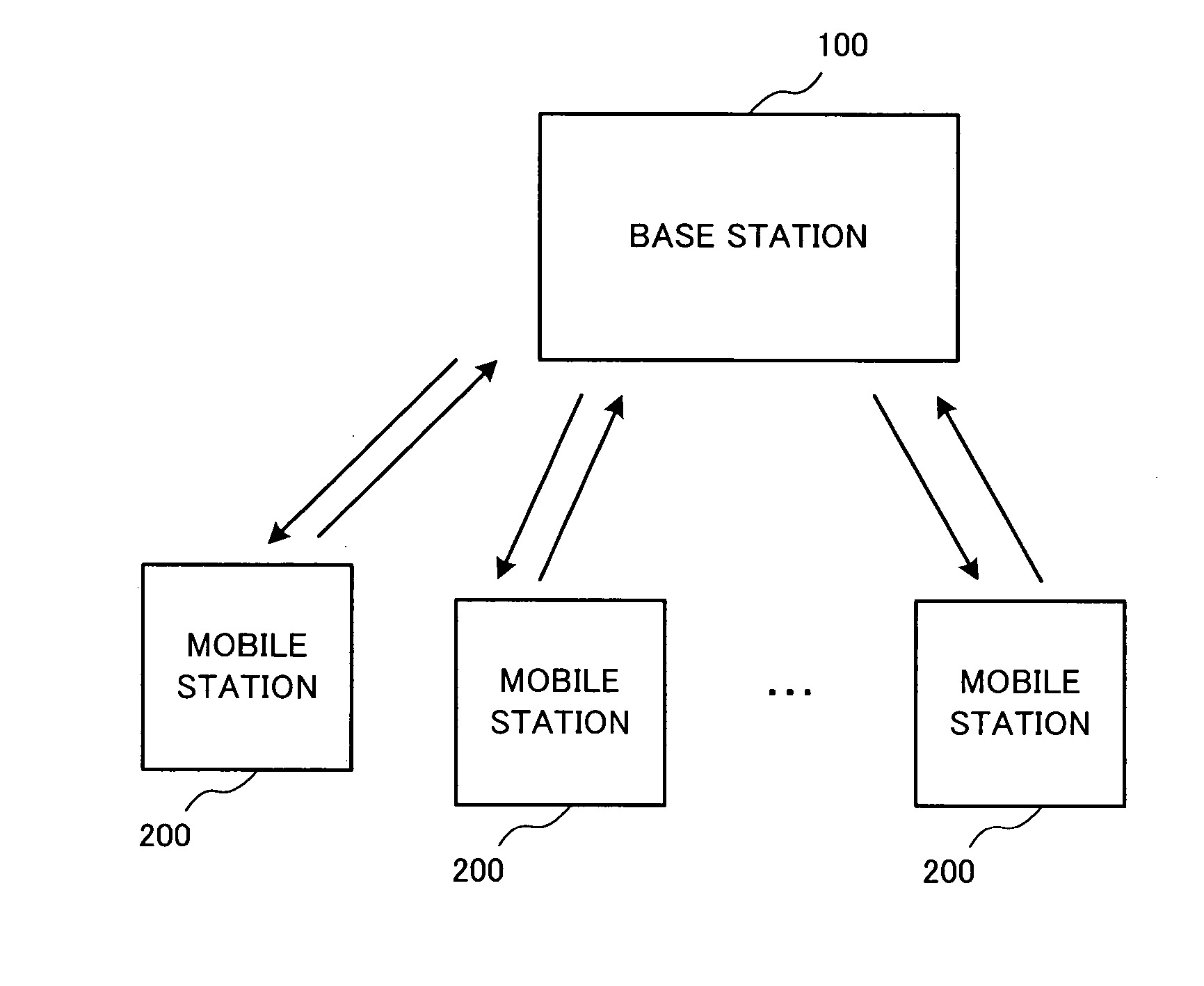
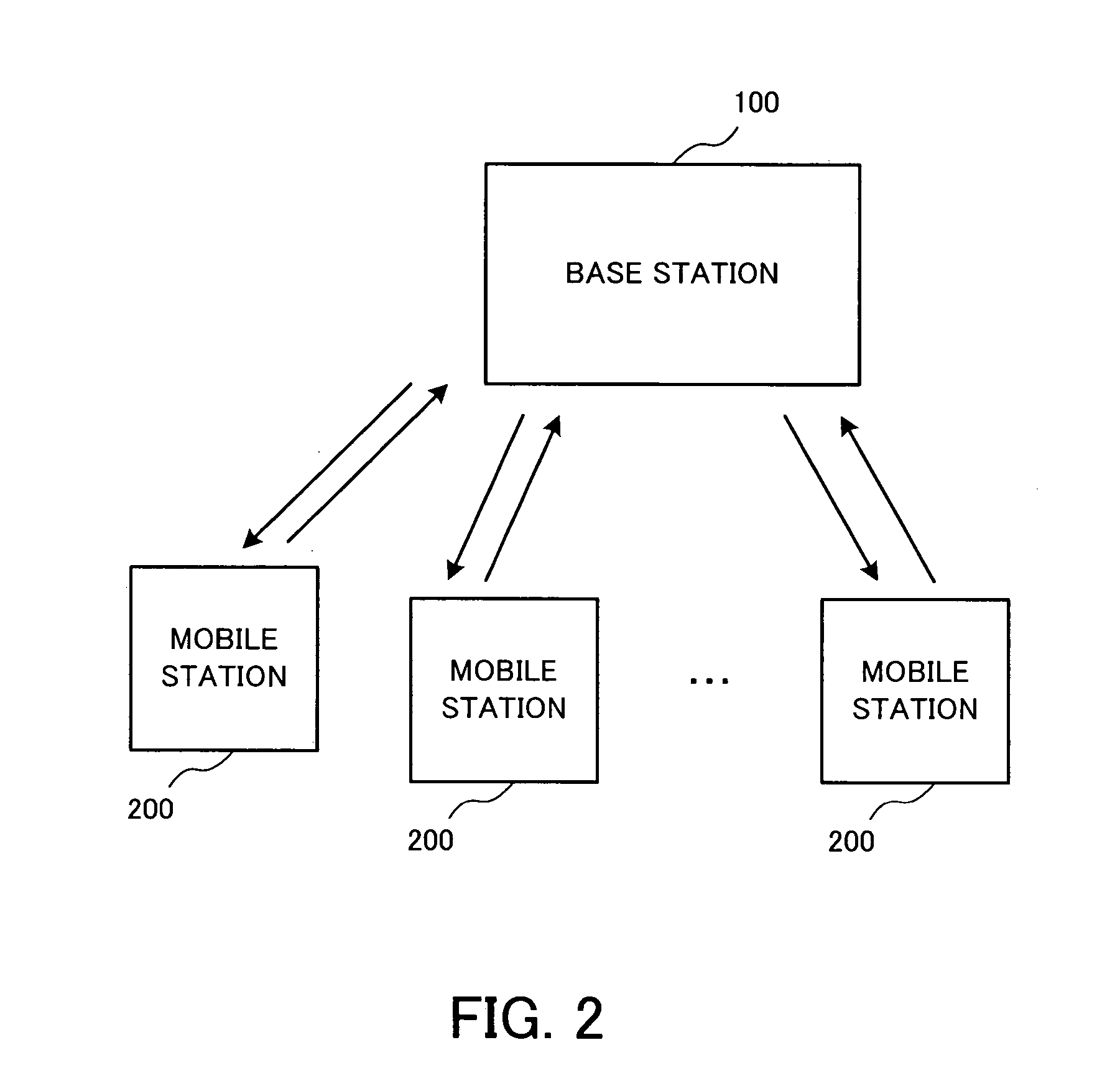
[0049]FIG. 2 is a block diagram schematically showing a data transmission system according to a
[0050] The data transmission system of this embodiment comprises a base station 100 and a plurality of (N) mobile stations 200 constituting a wireless network for exchanging packet-type data including a data channel and a control channel.
[0051] Each radio link is constituted by a downlink and an uplink. The downlink conveys data from the base station 100 to a mobile station 200, and the uplink conveys data in the opposite direction. In the following, the data channel and the control channel transmitted from the base station 100 to the mobile station 200 are referred to as “down data channel” and “down control channel”, respectively, and the data channel and the control channel transmitted from the mobile station 200 to the base station 100 are referred to as “up data channel” and “up control channel”, respectively. Further, since the multiple mobile stations 200 have an identical configur...
second embodiment
[0094] A data transmission system will be now described.
[0095] The following description is focused on the differences between the data transmission systems of the second and first embodiments, and description of the elements and functions common to the two embodiments is omitted.
[0096] The data transmission system of the second embodiment differs from the counterpart of the first embodiment in that an ACK / NACK signal, which is fed back to the base station for retransmission control, is used as information indicative of the communication quality of the down data channel, and comprises the base station 100 and a mobile station 200a.
[0097]FIG. 8 is a block diagram showing the mobile station according to the second embodiment.
[0098] In the data transmission system of the second embodiment, retransmission control is performed, and the CQI format is selected in accordance with the ACK / NACK signal which is used for the retransmission control.
[0099] To this end, the mobile station 200...
third embodiment
[0110] A data transmission system will be now described.
[0111] The following description is focused on the differences between the data transmission systems of the third and second embodiments, and description of the elements and functions common to the two embodiments is omitted.
[0112] The data transmission system of the third embodiment differs from the counterpart of the second embodiment in that the mobile station uses, as information indicative of the communication quality of the down data channel, a retransmission count which is notified from the base station 100 for the retransmission control, and comprises the base station 100 and a mobile station 200b.
[0113]FIG. 11 is a block diagram showing the mobile station according to the third embodiment.
[0114] At the mobile station 200b, the control channel demodulator / decoder 13 acquires information about the retransmission count from the control channel of the received packet 300.
[0115] The CQI pattern table 18 selects a CQI f...
PUM
 Abstract
Description
Claims
Application Information
 - R&D
- Intellectual Property
- Life Sciences
- Materials
- Tech Scout
- Unparalleled Data Quality
- Higher Quality Content
- 60% Fewer Hallucinations
Browse by: Latest US Patents, China's latest patents, Technical Efficacy Thesaurus, Application Domain, Technology Topic, Popular Technical Reports.
© 2025 PatSnap. All rights reserved.Legal|Privacy policy|Modern Slavery Act Transparency Statement|Sitemap|About US| Contact US: help@patsnap.com


