Method and steerable antenna apparatus

a technology of antenna apparatus and antenna head, which is applied in the direction of power management, spatial transmit diversity, network planning, etc., can solve the problems of affecting consuming a large quantity of battery power, so as to improve the quality of the communication link between the antenna and the electromagnetic signal source, and improve the performance of the amplifier.

Active Publication Date: 2020-09-01
SOFANT TECH
View PDF72 Cites 2 Cited by
  • Summary
  • Abstract
  • Description
  • Claims
  • Application Information

AI Technical Summary

Benefits of technology

[0010]A change in the location of the antenna affects the direction of the (typically fixed position) terrestrial electromagnetic signal source relative to the antenna. The location of the antenna also affects the signal propagation path (and therefore the signal attenuation and signal reflections incurred over the signal propagation path) taken by electromagnetic signals between the antenna and the terrestrial electromagnetic signal source. By selecting a steering data portion taking into account the determined location of the antenna and adjusting the principal communication direction of the steerable directional antenna taking into account the said selected steering data portion, the antenna can be brought into communication with the electromagnetic signal source (or the quality of the communications link between the antenna and the electromagnetic signal source can be improved) without having to perform a full scan of detectable electromagnetic signal sources when the antenna changes location (thereby saving processing and battery power). In addition, the steerable directional antenna can be steered towards a preferred communication direction for communicating with the terrestrial electromagnetic signal source much more quickly than if a full scan of detectable electromagnetic signal sources was required. This also helps to reduce the quantity of signal processing required thereby reducing electrical power consumption.
[0104]It may be that the method comprises adjusting (or the controller may be configured to adjusting) the frequency response of one or more antenna amplifiers configured to adjust a power level of (e.g. amplify) signals received by the antenna taking into account (or responsive to) the said frequency channel, typically to improve the performance of the amplifier at one or more frequencies of the said frequency channel. For example, the method may comprise adjusting the frequency response of a low noise amplifier configured to amplify signals received by the antenna taking into account (or responsive to) the said frequency channel, typically to improve the performance of the amplifier at one or more frequencies of the said frequency channel.

Problems solved by technology

The received signal strength is typically a function of distance and direction of the mobile device from the electromagnetic signal source, but the function can be more complex when obstructions are provided in the line of sight between the mobile device and the electromagnetic signal source, and when multi-path propagation occurs, for example due to signal reflections.
However, when mobile devices move, the antenna often needs to be steered back towards the electromagnetic signal source to maintain a wireless communications link of the required quality.
This scanning process typically takes time and uses a significant quantity of battery power.

Method used


Image

  • Method and steerable antenna apparatus
  • Method and steerable antenna apparatus
  • Method and steerable antenna apparatus

Examples


Embodiment Construction

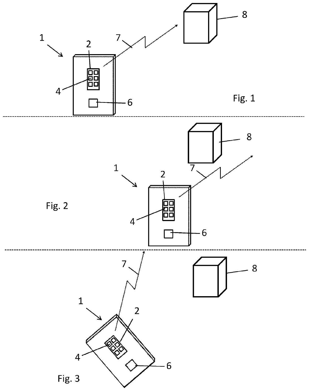
[0164]FIG. 1 is a schematic diagram of a human portable wireless communications device 1 (such as a smartphone, tablet, laptop or wearable computer) having a steerable directional antenna 2 comprising an array of antenna elements 4 in communication with a controller 6 comprising a computer processor. The positions of the antenna elements are fixed relative to a housing of the device 1. The antenna 2 is electronically steered by beamforming such that its principal communication direction 7 is aligned with a terrestrial radio frequency electromagnetic signal source 8 (such as a base station of a cellular communications network, a Wi-fi router or a Bluetooth beacon) with which the antenna 2 communicates (i.e. the antenna 2 transmits signals to and / or receives signals from the terrestrial electromagnetic signal source 8). For typical directional antennas of this type, the majority of electromagnetic signal power is transmitted within 60° of the principal communication direction, and mor...


PUM


Abstract

The invention provides a method of adjusting a principal communication direction of a steerable directional antenna for communicating with a terrestrial electromagnetic signal source, the method comprising: providing location specific steering data comprising one or more steering data portions, each of the steering data portions being specific to a respective location; determining a location of the steerable directional antenna; selecting a steering data portion from the location specific steering data taking into account the determined location of the antenna; determining an adjusted principal communication direction of the steerable directional antenna taking into account the said selected steering data portion; and adjusting the principal communication direction of the steerable directional antenna in accordance with the said adjusted principal communication direction.

Description

[0001]This application is the U.S. national phase of International Application No. PCT / GB2016 / 053909 filed 9 Dec. 2016, which designated the U.S. and claims priority to GB Patent Application No. 1522722.6 filed 23 Dec. 2015, the entire contents of each of which are hereby incorporated by reference.FIELD OF THE INVENTION[0002]The invention relates to: a method of adjusting a principal communication direction of a steerable directional antenna for communicating with a terrestrial electromagnetic signal source; steerable directional antenna apparatus; and a method of generating location specific steering data for a steerable directional antenna.BACKGROUND TO THE INVENTION[0003]Mobile communications devices use antennas for radio frequency wireless communication with terrestrial electromagnetic signal sources, such as cellular network base stations, Wi-fi access points and Bluetooth beacons. The strengths of signals received by the antennas from such electromagnetic signal sources vary ...

Claims


Application Information

Patent Timeline
Patent Type & Authority Patents(United States)
IPC IPC(8): H04B7/0413H04W16/28H04W52/28H04B7/0404H01Q3/26G01S1/04H04B7/06
CPCG01S1/042H01Q3/2611H04W52/283H04B7/0404G01S1/045H04B7/0617H01Q3/26H04W52/42H04W52/28H04B17/102H04W52/0254
Inventor EL-RAYIS, AHMED OSMANHARIDAS, NAKULARSLAN, TUGHRUL SATI
Owner SOFANT TECH
Why Eureka
Try Eureka