Radio communications system

a radio communication and system technology, applied in the field of radio communications systems, can solve the problems of degrading the communication quality of the terminal located on the boundary of cells produced by the base stations, intercell interference between the base stations, etc., to reduce the number of baseband modems 103 in the entire system, reduce interference between cells, and induce the effect of communication quality degradation

Inactive Publication Date: 2013-05-21
HITACHI LTD
View PDF9 Cites 1 Cited by
  • Summary
  • Abstract
  • Description
  • Claims
  • Application Information

AI Technical Summary

Benefits of technology

[0014]An object of the present invention is to reduce interference between cells which induces degradation of the communication quality in a broadband radio communications system. In order to achieve this object, according to the present invention, the entire radio communication band is divided into a plurality of subbands, and the combination of antennas configuring the cell is changed for each of the subbands, to thereby generate at least one subband where each terminal is not located at the cell boundary. Also, loads among the baseband modems 103 are dispersed, and the number of baseband modems 103 in the entire system is reduced, to thereby reduce the power consumption in the entire radio communications system. That is, an object of the present invention is to compatibly eliminate the boundaries between the cells in the entire radio communications system, and reduce the power consumption in the entire system due to the load dispersion. A specific object of the present invention will be described below.
[0016]In the cellular system shown in FIG. 38, the terminal 102-3 is located at a boundary of the cell 101-1 and the cell 101-2 of two cells. Even if any cell 101 is the serving cell, the terminal 102-3 receives a signal having the same level as that of a desired signal from another cell 101, or a signal having the same or higher level interfered with the cell 101. As a result, the communication quality of the terminal 102-3 is remarkably degraded. A first object of the present invention is to provide a system that eliminates a cell boundary for the purpose of preventing the communication quality from being degraded.
[0020]The radio unit switch 106 and the inter-base station switch 107 change over a path for transmitting a signal according to the traffic distribution of the terminal 102. The total traffic volume of the entire radio communications system is proportional to the number of terminals 102 that receive the service of the radio communications system in the entire radio communications system, and not proportional to the number of cells 101. Accordingly, a load exerted on the baseband modems 103 is dispersed according to the distribution of the terminals, thereby enabling the maximum traffic throughput (a margin to a mean traffic throughput) of the baseband modem 103 to one cell 101 to be reduced, or the number of baseband modems 103 to be reduced. As a result, the scale of the baseband modem 103 in the entire radio communications system can be reduced, and an electric power consumed by the entire baseband modem 103 can be reduced.

Problems solved by technology

In the radio communications system in which a plurality base stations communicate with terminals at the same frequency, there arises a problem of an intercell interference between the base stations.
Also, there arises a problem that the communication quality of a terminal located on the boundary of cells produced by the base stations is degraded.

Method used


Image

  • Radio communications system
  • Radio communications system
  • Radio communications system

Examples


first embodiment

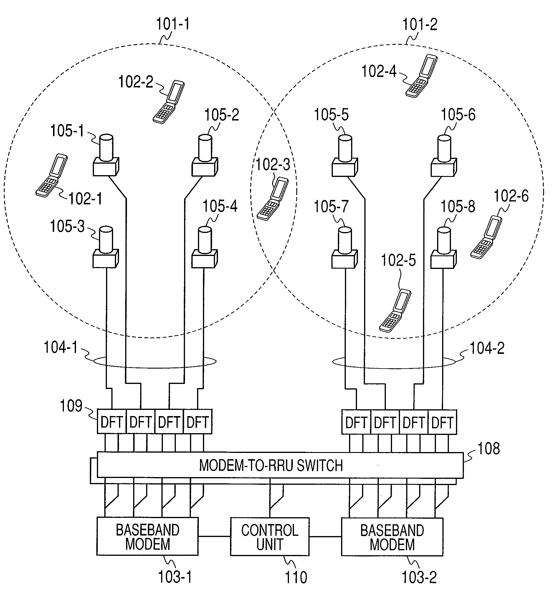
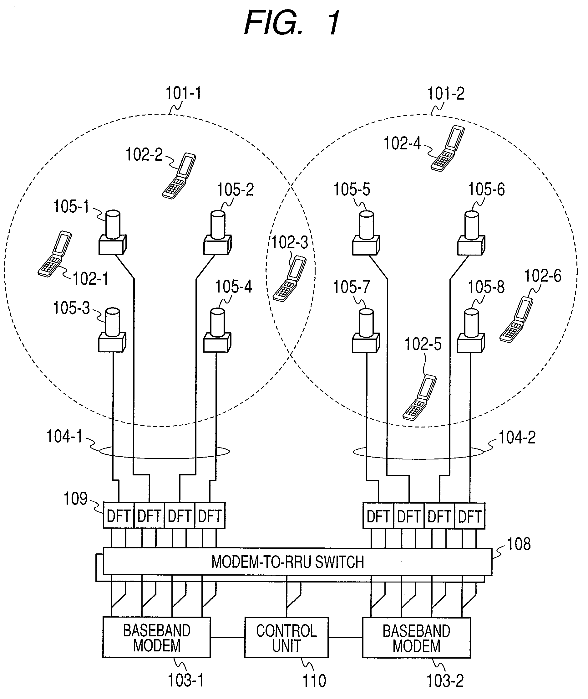
[0088]FIG. 1 is an explanatory diagram showing the configuration of a network system according to the present invention.

[0089]Cells 101-1 and 101-2, terminals 102-1 to 102-6, baseband modems 103-1 and 103-2, optical fibers 104-1 and 104-3, and front end portions 105-1 to 105-8 shown in FIG. 1 are identical with those in FIG. 38 or 39. The network system shown in FIG. 1 includes a modem-to-RRU switch 108, a DFT processing unit 109, and a control unit 110.

[0090]The baseband modem 103 shown in FIG. 1 has respective input / output ports allocated to a plurality of antennas, and one or plural base station modems 103 are arranged in the network system. The baseband modem 103 communicates a baseband signal for each of the subbands between the baseband modem 103 and the modem-to-RRU switch 108 (RRU: Remote Radio Unit), and also communicates a data bit series with a core network. Also, the modem 103 transmits traffic information for changing over the modem-to-RRU switch 108 to the control unit...

second embodiment

[0284]FIG. 29 is an explanatory diagram showing the configuration of a network system according to the present invention.

[0285]The first embodiment uses the OFDM radio communications system whereas the second embodiment shown in FIG. 29 uses the general multicarrier radio communications system. A difference from the configuration of the first embodiment resides in both ends of the optical fiber 104. When the optical fibers 104 are allocated to the signals of the respective carriers in the multicarrier radio communications system, individually, the radio communications system can be implemented by providing an optical modulator / demodulator and an electrical / optical converter which to each of the optical fibers. However, when the optical fiber is allocated to each of the carriers, because the costs for providing the optical fibers are increased, it is desirable to transmit the signals of the plural carriers by one optical fiber. For that reason, the radio communications system accordi...

third embodiment

[0288]FIG. 31 is an explanatory diagram showing the configuration of a network device according to the present invention.

[0289]The termination of the optical fibers 104 is the DFT processing units 109 in the first embodiment shown in FIG. 5, and the multicarrier coupling / separation units 111 in the second embodiment shown in FIG. 30.

[0290]In the configuration of the network device according to the third embodiment, each of the baseband modems 103 executes the signal processing of the subband being a control unit of the modem-to-RRU switch 108 at the plurality of antenna ports in a lump. According to the third embodiment, switching of each subband between the baseband modems 103 and the modem-to-RRU switches 108 is not required with the result that the array wiring in the same section is eased.


PUM


Abstract

A radio communications system includes at least one terminal communication unit having one antenna that conducts a radio communication with a plurality of terminals; and at least one baseband modem that generates and decrypts a data signal, a cell being configured by at least one of the antenna, wherein the baseband modem divides a radio frequency band used for the radio communication into two or more subbands, generates and decrypts the data signal specific to each of the divided subbands, and allocates the data signal specific to the subband to the terminal communication unit, and wherein the terminal communication unit receives the data signal specific to the subband generated by the baseband modem, and forms the cell of each the subband by the data signal specific to the received subband.

Description

CLAIM OF PRIORITY[0001]The present application claims priority from Japanese patent application JP 2009-057044 filed on Mar. 10, 2009, the content of which is hereby incorporated by reference into this application.FIELD OF THE INVENTION[0002]The present invention relates to a radio communications system, and more particularly to a radio communications system in which a plurality of base stations communicate with a terminal at the same frequency.BACKGROUND OF THE INVENTION[0003]With an aim to ensure data throughput of a terminal in a radio communication, it is essential to widen a radio band, and for the purpose of widening the band, research and development as well as standardization has been actively conducted on a multicarrier communication method.[0004]In 3GPP (3rd Generation Partnership Project being a radio communication standards body, standardization of the specification called “LTE (Long Term Evolution)” has been advanced.[0005]The LTE applies an OFDM (Orthogonal Frequency D...

Claims


Application Information

Patent Timeline
Patent Type & Authority Patents(United States)
IPC IPC(8): H04W72/00H04J11/00H04W72/04
CPCH04L5/001H04L5/0023H04L5/0032H04L5/006H04L5/0073H04L5/0035H04L5/0026H04L25/0228H04L25/0204
Inventor FUJISHIMA, KENZABUROTAKADA, MAYTSUNEHARA, KATSUHIKOTAMAKI, SATOSHISASAKI, SHINYAONO, GOUWANO, KOKI
Owner HITACHI LTD
Why Eureka
Try Eureka