Linear motion guide unit

a technology of motion guide and guide roller, which is applied in the direction of bearings, shafts and bearings, bearings, etc., can solve the problems of affecting the smooth rolling of the guide roller, the production of the lubricant-containing sleeve, and the difficulty of adjusting the sleeve, so as to achieve the effect of easy adjustment, good deflection or flexure, and steady circulation of the roller over the long-term operation

Active Publication Date: 2007-03-29
NIPPON THOMPSON
View PDF2 Cites 19 Cited by
  • Summary
  • Abstract
  • Description
  • Claims
  • Application Information

AI Technical Summary

Benefits of technology

[0014] The present invention has for its primary object to overcome the major challenges as stated earlier, and to further develop the linear motion guide unit disclosed in the commonly assigned Japanese senior patent application recited above, in which the sleeve or tubular member for the preparation of the return passage is made of a tubular composition that is made up of a tubular skeleton and a compact of porous structure. More particularly, the present invention provides a linear motion guide unit in which a clearance is left between a porous compact and a flexible spine of the tubular skeleton for the return passage while a relief portion is made on the flexible spine for alleviating an stress applied on the flexible spine by circulating motion of the cylindrical rollers, and the porous compact with pores filled with lubricant fits into the tubular skeleton in a way exposing itself to a return passage to come into rolling-contact with more than one rolling element of roller, keeping the positive application of lubricant around the roller more sustainable. Moreover, the provision of the relief portion on the flexible spine serves to relieve the flexible spine of the stress or impact caused by rolling operation of the roller in the return passage, lessening the need for mechanical strength in the tubular skeleton as well as getting the long-lasting smooth travel of the roller in the circulating circuit with accompanying reduced maintenance or maintenance-free for lubrication.
[0017] In an aspect of the present invention, there is provided a linear motion guide unit in which the porous compact fits over the flexible spine in such a relation that a clearance remains between an outward surface of at least the flexible section of the flexible spine and an inward surface of the porous compact to permit the flexible spine getting flexed to relieve an stress that is exerted on the flexible spine by circulating motion of the rollers. In another aspect of the present invention, the relief portions are larger in transverse section than the flexible middle section lying between the relief portions.
[0022] With the linear motion guide unit constructed as stated earlier, especially, the flexible spines are each composed of relief portions spaced apart from one another and merged with forward and aft ends of the tubular skeleton, one to each end, and the flexible middle section extending between the relief portions. As an alternative, additional relief portions may be further made midway in the flexible middle sections of the flexible spines. In any version, the construction that flexible middle sections are connected to the ends of the tubular skeleton through the relief portions makes the flexible spines possible to bear much deflection or flexure. Thus, the relief portions contributes to well alleviation of the deflection caused in the flexible middle section owing to the rolling movement of the rollers, making sure of the steady circulation of the rollers over the long-term operation. In particular, the clearance between the inward surface of the porous compact and the outward surface of the flexible spine leads the flexible spine into following universally the stress exerted on the flexible spine by the rolling movement of the rollers, deflecting to relieve good the stress, thereby making sure of smooth circulation of the rollers.
[0023] With the linear motion guide unit according to the present invention, moreover, if the rollers run through the return passage with coming into rolling-contact with porous compact, lubricant impregnated in the porous compact is transferred around the rollers, making certain of sustainable application of lubricant on the rollers rolling through the return passage to realize substantive maintenance-free condition for lubrication. Thus, the linear motion guide unit constructed as stated earlier is expected to serve adequate lubrication in particular operating environments, for example under high-temperature and so on, or in clean rooms required less consumption of lubricant. Moreover, the linear motion guide unit of the present invention, because of the maintenance-free operation requiring no maintenance schedule for lubrication, may well respond to the machines that needs lubrication quality enough to lessen the frictional resistance encountered when the rollers slide over the load race to actuate the slider relatively to the guide rail with high-speed, high-cyclic operating requirements

Problems solved by technology

Correspondingly, the linear motion guide units used in the advanced machinery are also challenged to keep the consumption of lubricant to a minimum, along with keeping linear motion guide units virtually maintenance free for lubrication over long-lasting operation.
With the linear motion guide unit in which rollers are selected as the rolling elements, meanwhile, alignment problems to guide rollers in good rolling order without leaning in rolling posture are more encountered, compared with the construction using balls.
Production of the lubricant-containing sleeve has thus required special equipment and complicated process.
Thus, the porous members could not rid themselves of mechanical deformation when the flexible spines of the tubular skeleton experienced any distortion.
Such deformation that might occur in the porous members was undesired in aspects of keeping the circulation of the rollers smoother as well as the positive maintenance-free operation more sustainable.
There, it remains a major challenge to further develop the tubular composition for the turn passage in the slider so as to provide the linear motion guide unit improved in the application of lubricant around the rolling elements as well as smooth guidance of the rolling elements in the return passage.

Method used


Image

  • Linear motion guide unit
  • Linear motion guide unit
  • Linear motion guide unit

Examples


Embodiment Construction

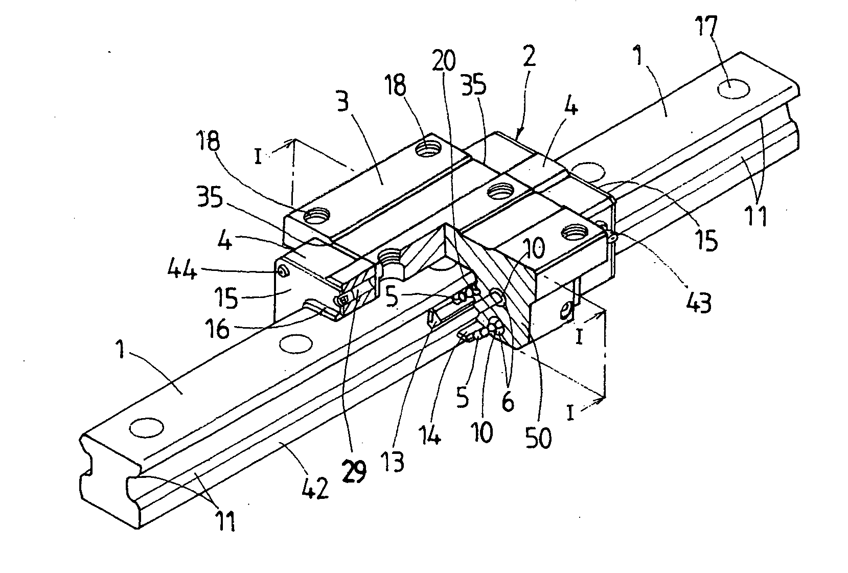
[0046] Referring now in detail to the drawings, the linear motion guide unit according to the present invention will be explained below. The linear motion guide unit according to the present invention is adapted for use in any relatively sliding components in machinery as diverse as various robots, semiconductor manufacturing machines, precision machines, measurement / inspection instruments, medical instruments, micromachines, machine tools, and so on, and more particular constructed to make sure of maintenance-free operation for better lubricant application to the rolling elements, with using a tubular composition for return passage high in mechanical strength to ensure smooth rolling of the rolling elements through a recirculating circuit with accuracy for a long-lasting service life.

[0047] The present invention contemplates the lubricant application system on the rolling elements of rollers in the linear motion guide unit disclosed in the commonly assigned Japanese Patent Laid-Op...


PUM


Abstract

A linear motion guide unit is disclosed in which a tubular composition to provide a return passage is high in mechanical stiffness and also makes certain of sustainable application of lubricant to rolling elements rolling through the return passage, thereby ensuring proper lubrication under maintenance-free operation. The tubular composition to make the return passage is composed of a tubular skeleton to guide the rollers, and a porous compact impregnated with lubricant. The tubular skeleton is made up of forward and aft ends, a lengthwise column and a flexible spine, which extend between the ends. The flexible spine includes lengthwise opposite relief portions and a flexible middle section, which fit into the porous compact with separating from the porous compact to make a clearance between them. The flexible spine deflects as the rollers roll through the return passage, permitting the rollers coming into touch with the porous compact to lubricate the rollers.

Description

FIELD OF THE INVENTION [0001] The present invention relates to a linear motion guide unit comprised of an elongated guide rail, and a slider that is allowed to move on the elongated guide rail relatively to the guide rail by virtue of more than one rolling element. BACKGROUND OF THE INVENTION [0002] Linear motion guide units conventionally incorporated in diverse machinery are ordinarily fed with lubricant every a preselected interval based on maintenance schedules to make certain of forming the lubricant film separating a rolling element from a load-carrying race, ensuring sustainable smooth rolling motion of the rolling element throughout a circulating circuit. Meanwhile, modern advanced machines and instruments are increasingly needed to work virtually in maintenance-free operating conditions from many aspects of conserving energy as well as keeping running cost and maintenance cost of equipment reasonable. Correspondingly, the linear motion guide units used in the advanced machi...

Claims


Application Information

Patent Timeline
Patent Type & Authority Applications(United States)
IPC IPC(8): F16C29/06
CPCF16C29/0611F16C33/6648F16C33/6611F16C29/065
Inventor KUWABARA, HIDEKIIWATA, TAMOTSU
Owner NIPPON THOMPSON
Why Eureka
Try Eureka