
Fluid circulation type hydrodynamic pressure bearings

a technology of hydrodynamic pressure bearings and fluid circulation, which is applied in the direction of bearings, shafts and bearings, rotary bearings, etc., can solve problems such as oil leakag

Inactive Publication Date: 2007-03-29
SAMSUNG ELECTRO MECHANICS CO LTD
View PDF15 Cites 6 Cited by
  • Summary
  • Abstract
  • Description
  • Claims
  • Application Information

AI Technical Summary

Benefits of technology

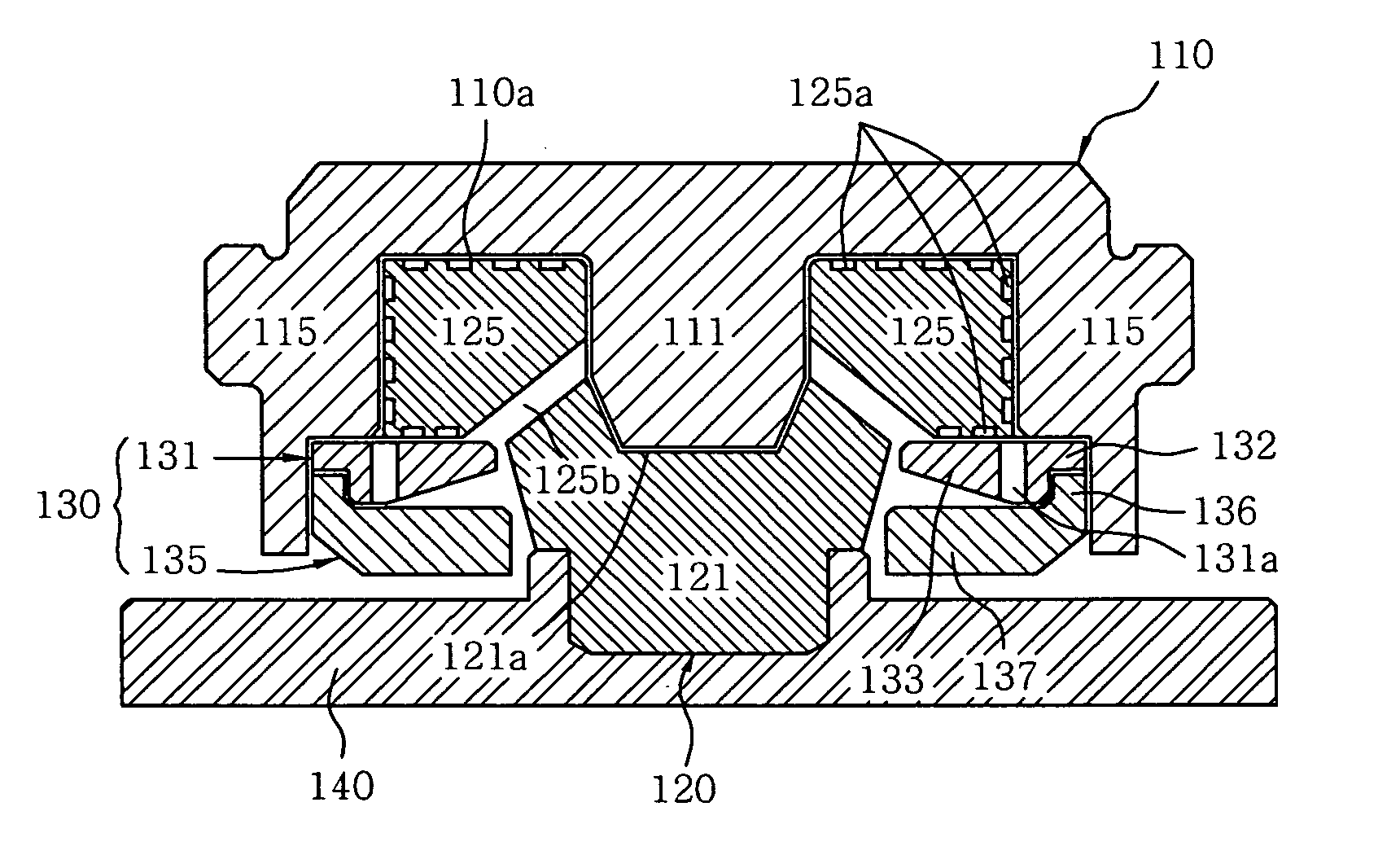
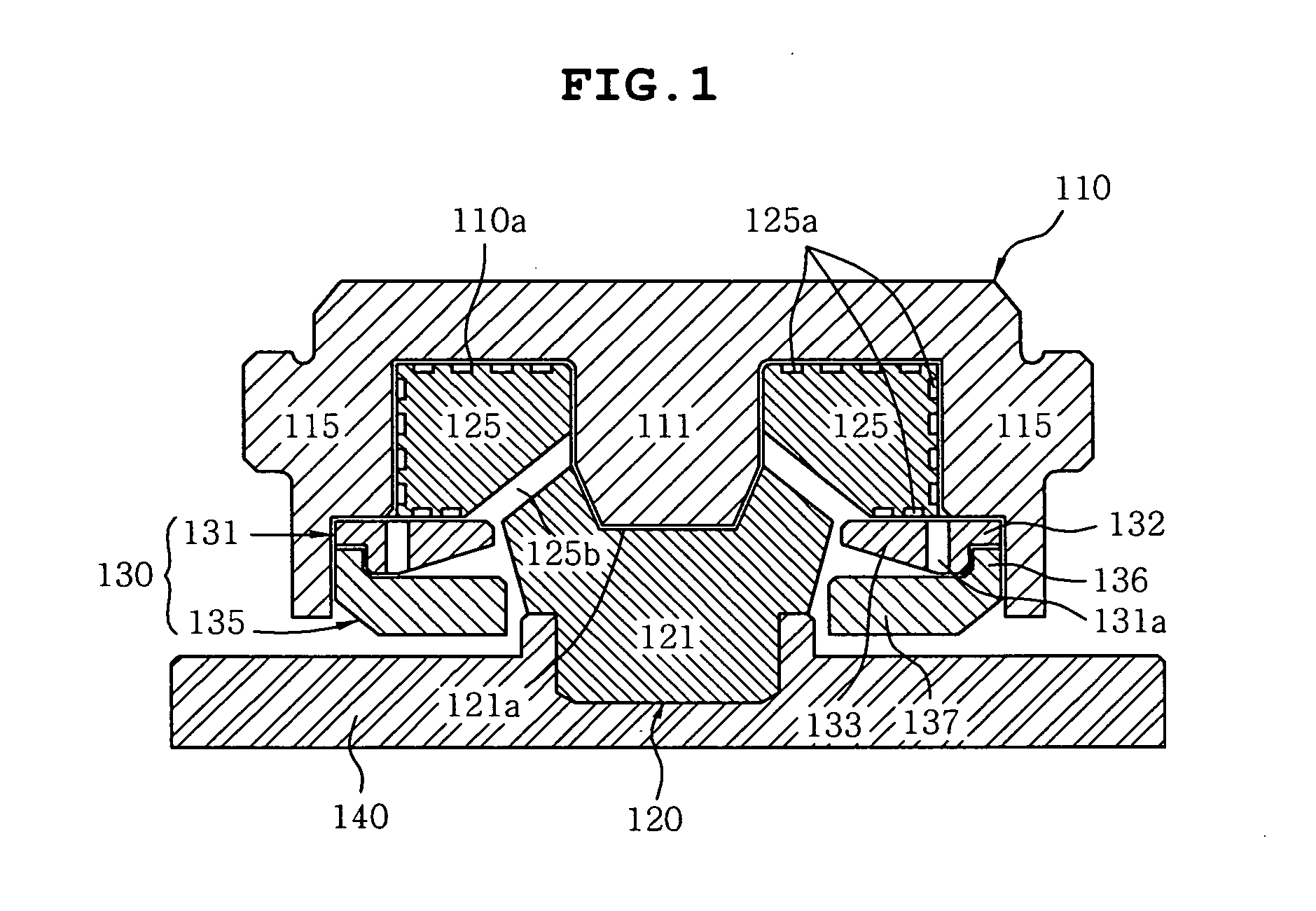
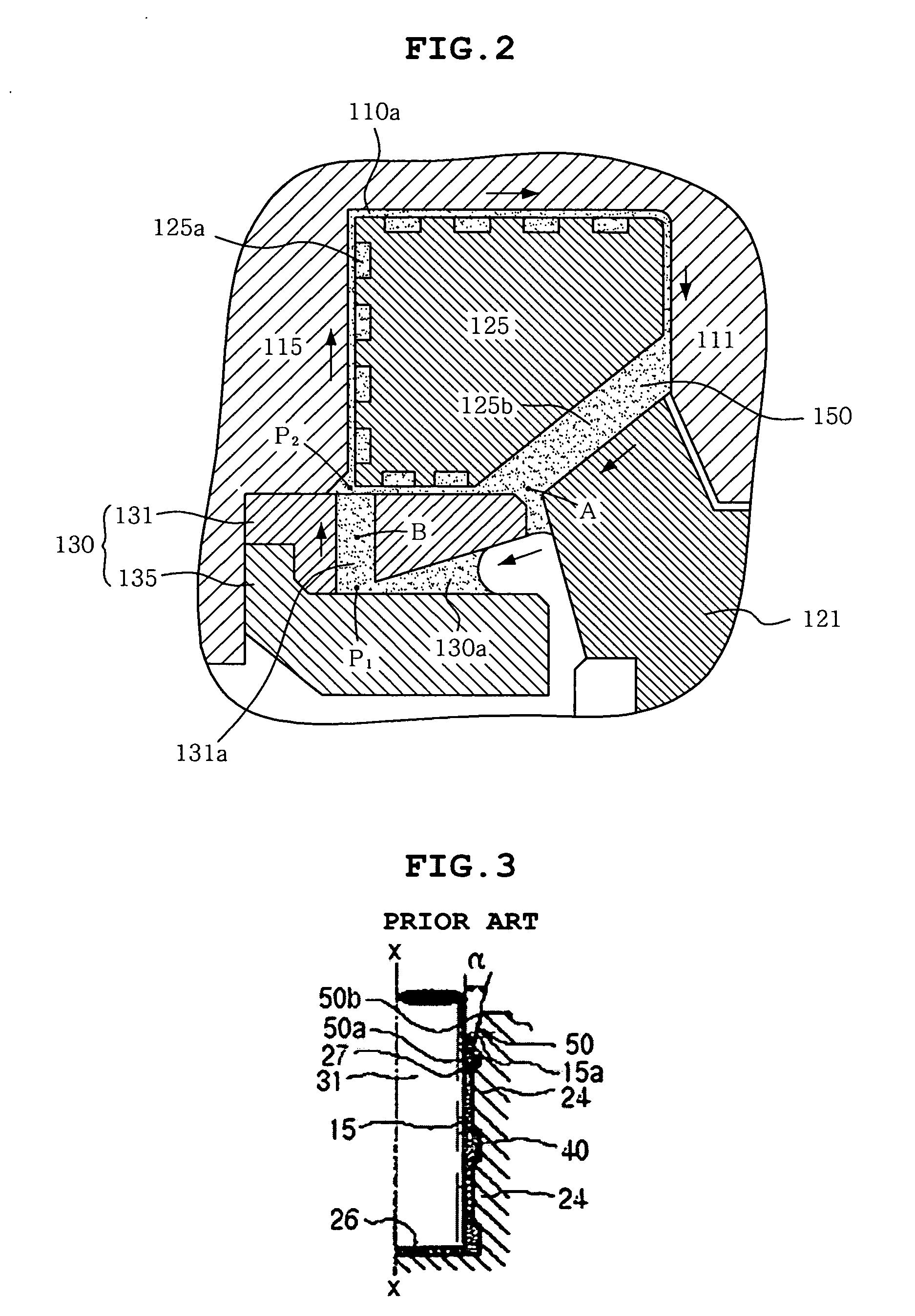
[0011] One object of the present invention is to provide a hydrodynamic pressure bearing enabling to prevent an outward leakage of the fluid regardless of the change of the surrounding condition by repeatedly circulating the fluid in the bearing through a fluid circulating member.

Problems solved by technology

However, the sealing system described above has a drawback that may not keep the oil in the bag part 40 and then raise oil leakage if variation of conditions such as viscosity of oil or heat generated by the rotation of the shaft and the like exceeds the design criteria thereof.

Method used


Image

  • Fluid circulation type hydrodynamic pressure bearings
  • Fluid circulation type hydrodynamic pressure bearings
  • Fluid circulation type hydrodynamic pressure bearings

Examples


Embodiment Construction

[0022] Reference will now be made in detail to the preferred embodiments of the present invention, examples of which are illustrated in the accompanying drawings.

[0023] As shown in FIG. 1, a hydrodynamic pressure bearing 100 according to a preferred embodiment of the present invention comprises a hub 110, a sleeve 120 and a fluid circulating member 130.

[0024] The hub 110 serves to mount recording media (not shown) such as a hard-disk thereon and rotate it, and it has an annular hydrodynamic pressure generating space 110a being formed in central portion thereof. Also, the hub 110 has an shaft portion 111 and a rim portion 115 formed on the inside and outside respectively with respect to the hydrodynamic pressure generating space 110a.

[0025] The shaft portion 111 is integrally extended from an inner central portion of the hub 110, and an end portion thereof is tapered to be easily rotated.

[0026] The rim portion 115 is integrally extended from a shaft portion 111 of the hub 110, an...


PUM


Abstract

The bearing of the present invention comprises a hub 110 for driving recording media; a sleeve 120 for rotatably support the hub 110 to define a hydrodynamic pressure generating space 110a between the hub 110 and the sleeve 120, the sleeve 120 being formed with a fluid outlet 125b through which the fluid passes at the predetermined position; a plurality of recesses 125a for generating hydrodynamic pressure, the recesses 125 being formed on at least one of the hub 110 and the sleeve 120 to be opened toward the hydrodynamic pressure generating space 110a; and a fluid circulating member 130 for circulating the fluid out-flowing from the fluid outlet 125b to the hydrodynamic pressure generating space 110a, the member 130 being fixedly combined with the hub 110 to slidably support the sleeve 120.

Description

BACKGROUND OF THE INVENTION [0001] 1. Field of the Invention [0002] The present invention relates to a hydrodynamic pressure bearing, and more particularly, to a hydrodynamic pressure bearing enabling to repeatedly circulate fluid for generating hydrodynamic pressure therein. [0003] 2. Description of the Related Art [0004] A hydrodynamic pressure bearing serves to generate the driving force of a spindle motor being installed in a hard disk driver and the like. One of examples, Japanese Patent Registration No. 2,937,833 discloses ┌Bearing seal system┘, which is illustrated with reference to FIGS. 3 and 4. [0005] As shown, the bearing seal system is composed of a shaft 31 and a radial bearing section 24. [0006] The radial bearing section 24 is arranged on the shaft-orientations outside, and provided with a clearance change section 50 for preventing leakage of the oil 15 present between the bearing section 24 and the shaft21. Also, an oil surface section 15a of the oil 15 filled up the...

Claims


Application Information

Patent Timeline
Patent Type & Authority Applications(United States)
IPC IPC(8): F16C32/06
CPCF16C2370/12F16C33/1085F16C17/107F16C33/745F16C32/06
Inventor LIM, TAE HYEONG
Owner SAMSUNG ELECTRO MECHANICS CO LTD
Learn More