Oil pumping device of hermetic compressor

a technology of oil pump and compressor, which is applied in the direction of machines/engines, rotary/oscillating piston pump components, liquid fuel engines, etc., can solve the problems of reducing centrifugal force, increasing the abrasion of sliding parts, and unable to smoothly pump the oil

Active Publication Date: 2007-03-29
LG ELECTRONICS INC
View PDF4 Cites 28 Cited by
  • Summary
  • Abstract
  • Description
  • Claims
  • Application Information

AI Technical Summary

Problems solved by technology

If the oil pump of such a compressor pulls oil from the bottom of the compressor casing, this can result in the sliding parts being supplied with more refrigerant than oil.
As a result, abrasion of the sliding parts may be increased due to lack of oil.
However, during low-speed operations, the centrifugal force decreases, and it may be impossible for the oil pump 9 to smoothly pump the oil.
Therefore, during low speed operations, abrasion between components is caused by lack of oil in the sliding parts, and reliability and performance of the compressor may be reduced.
This increases abrasion caused by lack of oil in each of the sliding parts.
Therefore, reliability and performance of the compressor are seriously reduced.

Method used


Image

  • Oil pumping device of hermetic compressor
  • Oil pumping device of hermetic compressor
  • Oil pumping device of hermetic compressor

Examples


first embodiment

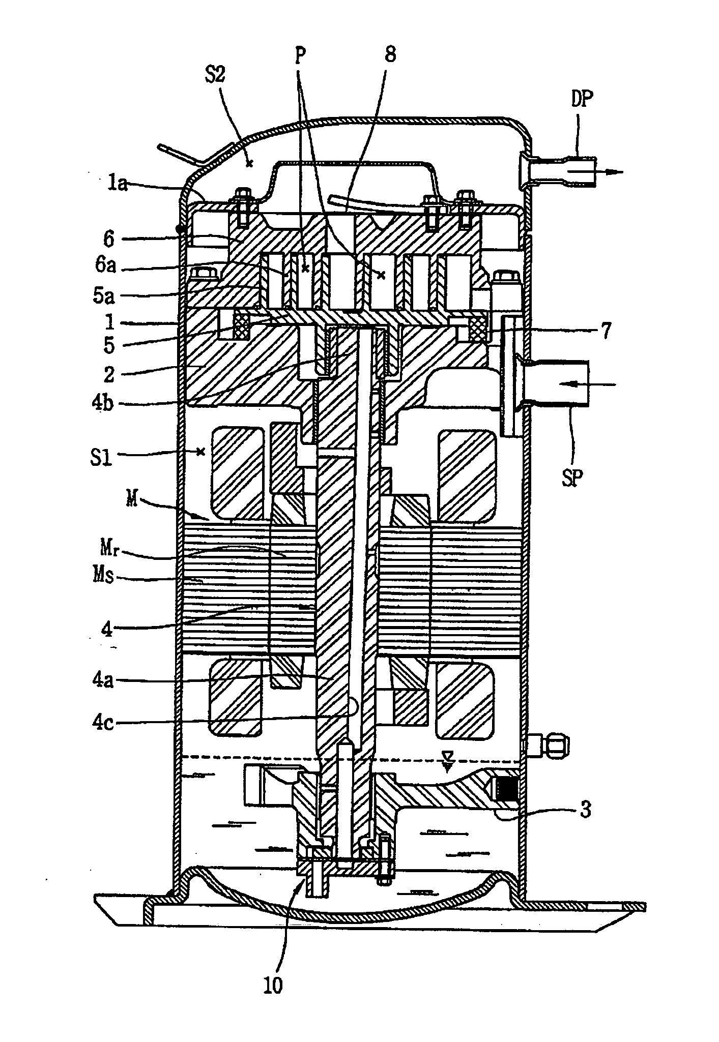
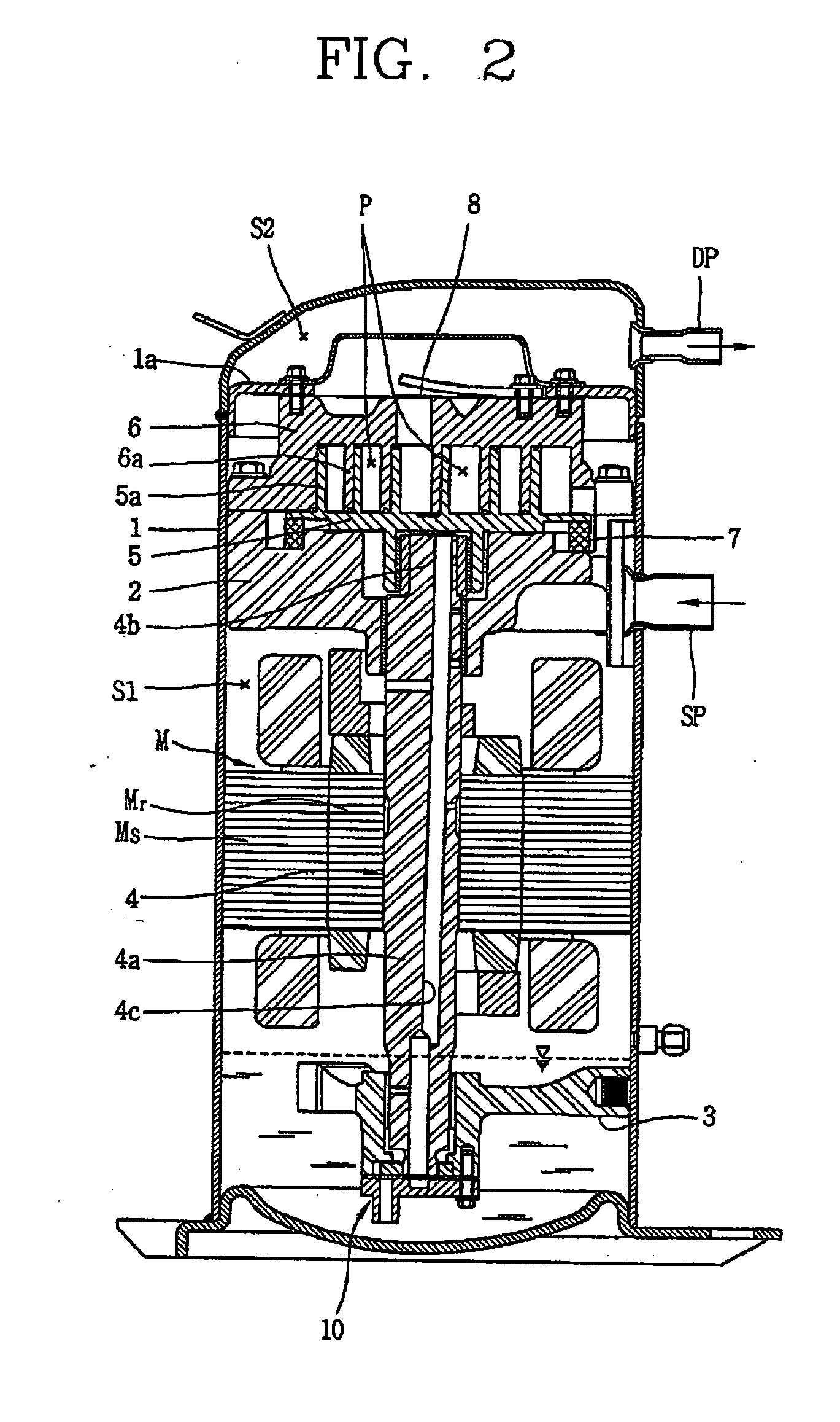
[0030] As shown therein, a scroll compressor according to the present invention includes a casing 1 filled with a predetermined amount of oil. A main frame 2 and a sub-frame 3 are fixed to upper and lower sides, respectively, inside the casing 1. A driving shaft 4 coupled with a rotor of a driving motor (M) is mounted between the main frame 2 and the sub-frame 3 so as to transmit a rotary force. An orbiting scroll 5 is mounted on the main frame 2, coupled with the driving shaft 4, and performs an orbiting motion. A fixed scroll 6 having a spiral wrap 6a, is engaged with a wrap 5a of the orbiting scroll 5 so as to form a plurality of compression chambers (P). The fixed scroll 6 is fixed to an upper surface of the main frame 2. An Oldham's ring 7 is installed between the orbiting scroll 5 and the main frame 2 so as to prevent rotation of the orbiting scroll 5 and allow the orbiting scroll to perform an orbiting motion. A check valve 8 is coupled to a rear surface of an end plate porti...

second embodiment

[0045] The oil to be filled in the casing 1 has a mixed degree of oil and refrigerant that varies according to oil types, refrigerant types, or external conditions. In the second embodiment, the amount of oil pumped can vary according to positions of the suction holes 121a and 121b of the oil pump 100. For example, as shown in FIG. 8, when the oil and the refrigerant are completely mixed with each other, regardless of whether the suction holes of the pump cover 120 are formed at only the lower end of the suction projection 121 or both the first suction hole 121a at the bottom surface and the second suction hole 121b at the side surface, the refrigerant and the oil are sucked together to thereby smoothly lubricate the sliding parts of the compressor.

[0046] On the other hand, as shown in FIG. 9, when a ‘double-layer separation phenomenon’ occurs, that is, the refrigerant and the oil are not completely mixed with each other, the refrigerant having a relatively high density is deposited...

third embodiment

[0048] In this third embodiment, when the oil and the refrigerant are almost completely mixed with each other, the mixed refrigerant and the oil are sucked together through both suction holes 221a and 222a. On the other hand, when the oil and the refrigerant are separated from each other as a double layer, refrigerant is sucked through the suction hole 221a of the first suction projection 221, which is relatively deeply extended, while oil is sucked through the suction hole 222a of the second suction projection 222, which is relatively shallowly extended. Therefore, regardless of the degree of mixing of the oil and refrigerant, oil can always be pumped, thereby increasing reliability of the compressor.

[0049] When a separate second suction projection is used, the second suction projection may have various shapes. The shape can be used to help control the amount of oil that is pumped. For example, as shown in FIG. 11, a first suction projection 321 is deeply extended and has a first s...


PUM


Abstract

A hermetic compressor uses an oil pump that includes a trochoid gear. Therefore, regardless of the rotation speed of a driving motor of the compressor, a sufficient amount of oil can always be pumped. The oil pump unit may include a plurality of suction holes with openings at different heights. If the refrigerant and oil separate, at least one of the openings will admit oil into the oil pump unit, to ensure lubricating oil is supplied to the moving parts of the compressor.

Description

[0001] This application claims priority under 35 U.S.C. §119 to Korean Patent Application No. 2005-0090826, filed in Korea on Sep. 28, 2005, the entirety of which is hereby incorporated by reference. BACKGROUND OF THE INVENTION [0002] 1. Field of the Invention [0003] The present invention relates to an oil pump of a hermetic compressor, and more particularly, to an oil pumping device of a hermetic compressor using a trochoid pump so as to pump oil by using a variation in volume. [0004] 2. Description of the Background Art [0005] In, general, a hermetic compressor includes a compression part and a motor part inside a hermetic casing. When the compression part operates by a driving force of a motor part, the compressor part sucks, compresses, and discharges refrigerant. Recently, in order to minimize environmental pollution, such as global warming, the use of CFC-based refrigerant has been gradually regulated in the hermetic compressor field. Therefore, in order to minimize the enviro...

Claims


Application Information

Patent Timeline
Patent Type & Authority Applications(United States)
IPC IPC(8): F03C2/00F01C1/02F04C29/02
CPCF04C2/102F04C29/025F04C23/008F04C18/0215F04C18/02F04C29/02
Inventor LEE, DONG-SOOJUNG, CHUL-SUSUH, JEONG-HWANKIM, SEUNG-YUP
Owner LG ELECTRONICS INC
Why Eureka
Try Eureka