Wear-resistant elements and method of making same

a technology of wear-resistant elements and elements, applied in the direction of solid-state diffusion coating, coating, metallic material coating process, etc., can solve the problems of difficult to maintain desired oil-retaining properties, surface wear uniformity, and possibility of seizing, so as to promote nitriding treatment, high-reliable wear-resistant elements, and enhance hardness

Inactive Publication Date: 2007-03-29
KAWASAKI NITRIDING +1
View PDF2 Cites 5 Cited by
  • Summary
  • Abstract
  • Description
  • Claims
  • Application Information

AI Technical Summary

Benefits of technology

[0020] The present invention has the above-described features and offers the following effects.
[0021] A material is first shaped and sintered into a compact using iron-based alloy powder containing Cr or using alloy powder in which at least one metallic element selected from Mn, Ti and V is contained in iron-based alloy powder containing Cr, and a nitriding treatment having no carburizing action is subsequently conducted to the compact, thereby causing a surface of the compact to have a mixed structure of a compound layer, a diffused layer, and a matrix. Accordingly, the amount of processing of the soft matrix portion increases during the finishing of the wear-resistant element to thereby form minute hollows, i.e., minute oil holes. When the wear-resistant element is in operation, slight wear occurs in the soft matrix portion to thereby form oil holes, making it possible to realize a highly reliable wear-resistant element free from seizing.
[0022] Furthermore, when the alloy powder in which at least one metallic element selected from Mn, Ti and V is contained in iron-based alloy powder containing Cr is used, the compound layer and the diffused layer come to contain at least one of Cr, Mn, Ti and V. Fe or Cr acts to ensure a desired hardness, Mn acts to further enhance the hardness, Ti acts to promote the nitriding treatment, and V acts to make the nitriding depth deep, making it possible to further enhance the reliability of the wear-resistant element.
[0023] Also, iron-based alloy powder containing Cr is first shaped and sintered into a compact, which is in turn quenched and tempered, and a nitriding treatment having no carburizing action is subsequently conducted to the compact, thereby causing a surface of the compact to have a mixed structure of a compound layer, a diffused layer, and a matrix of a sorbite structure. Accordingly, the amount of processing of the soft matrix portion increases during the finishing of the wear-resistant element to thereby form minute hollows, i.e., minute oil holes. When the wear-resistant element is in operation (relative frictional motion), slight wear occurs in the matrix portion that is softer than the compound layer and the diffused layer to thereby form oil holes. In addition, because the quenching and tempering increase the hardness of the matrix structure, a subsequent nitriding treatment further enhances the hardness of the compound layer and the diffused layer, making it possible to realize a seizing-free and highly reliable wear-resistant element having an increased wear resistance.
[0024] Alternatively, a material is first shaped and sintered into a compact, which is in turn quenched and tempered, a nitriding treatment having no carburizing action is subsequently conducted to the compact, and a surface of the compact is then partially removed, thereby causing the surface of the compact to have an Fe—Cr—N compound layer and also have variations in hardness. Accordingly, the amount of processing of the soft matrix portion increases during the finishing of the wear-resistant element to thereby form minute hollows, i.e., minute oil holes. When the wear-resistant element is in operation (relative frictional motion), slight wear occurs in the soft portions to thereby form oil holes. The oil holes act to enhance the lubricating properties, while the portion other than the oil holes, i.e., the portion of the compound layer acts to maintain the wear resistance, making it possible to enhance the reliability of the wear-resistant element.

Problems solved by technology

Accordingly, if a wear-resistant element such as a vane for use in a compressor is made of one of such materials, the vane tends to wear uniformly during operation of the compressor.
As a result, the surface is hard to maintain desired oil retaining properties, and there is a possibility of seizing.

Method used


Image

  • Wear-resistant elements and method of making same
  • Wear-resistant elements and method of making same
  • Wear-resistant elements and method of making same

Examples


example 1

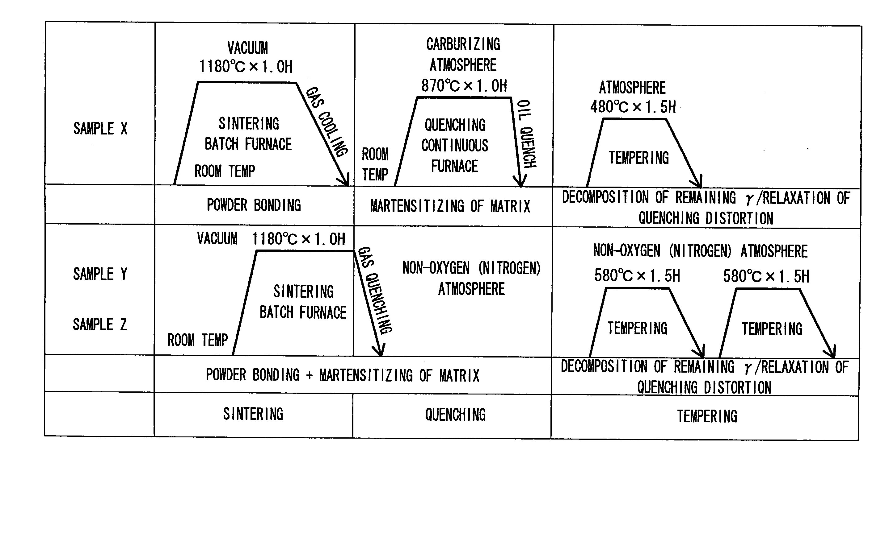
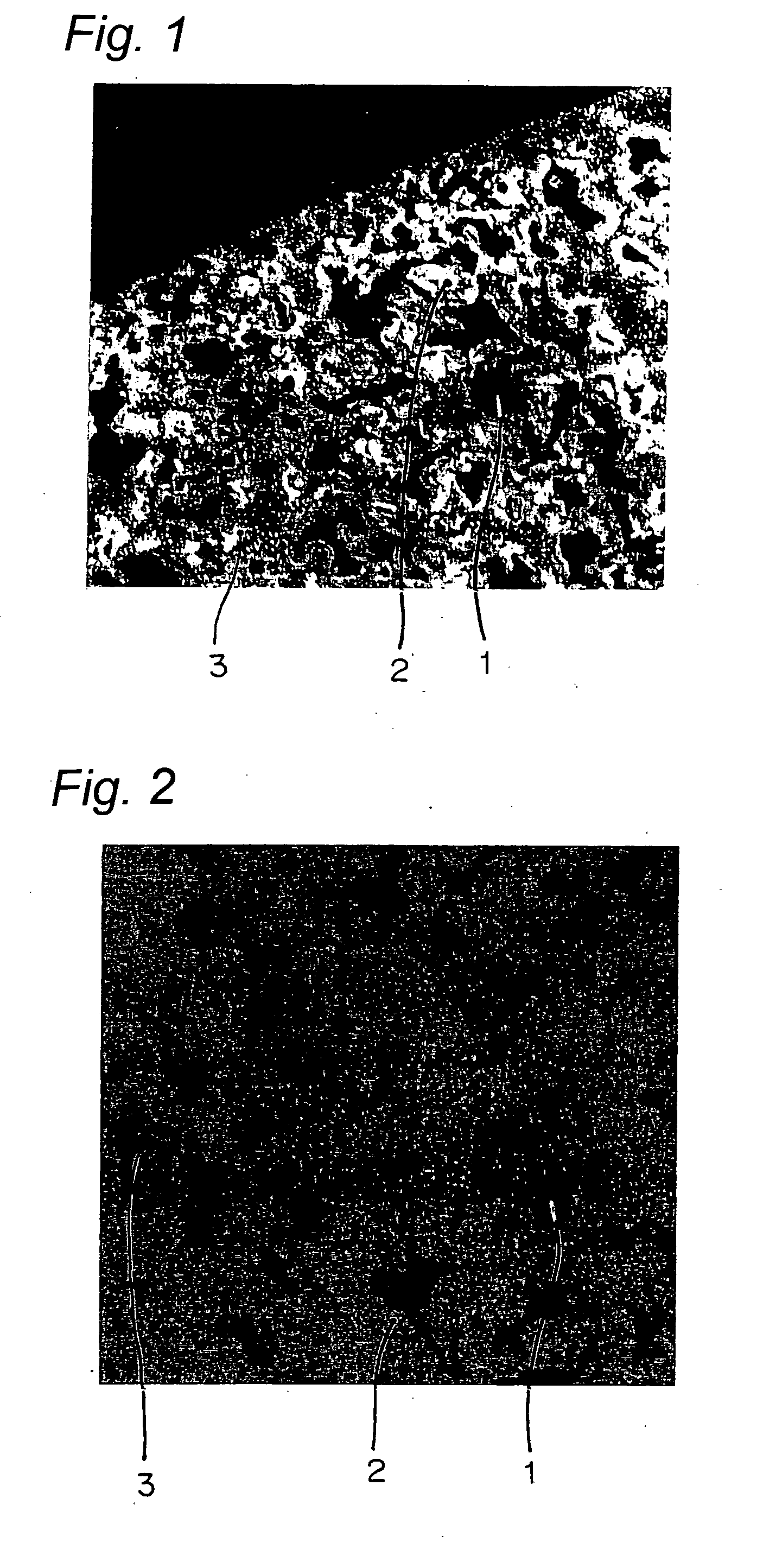
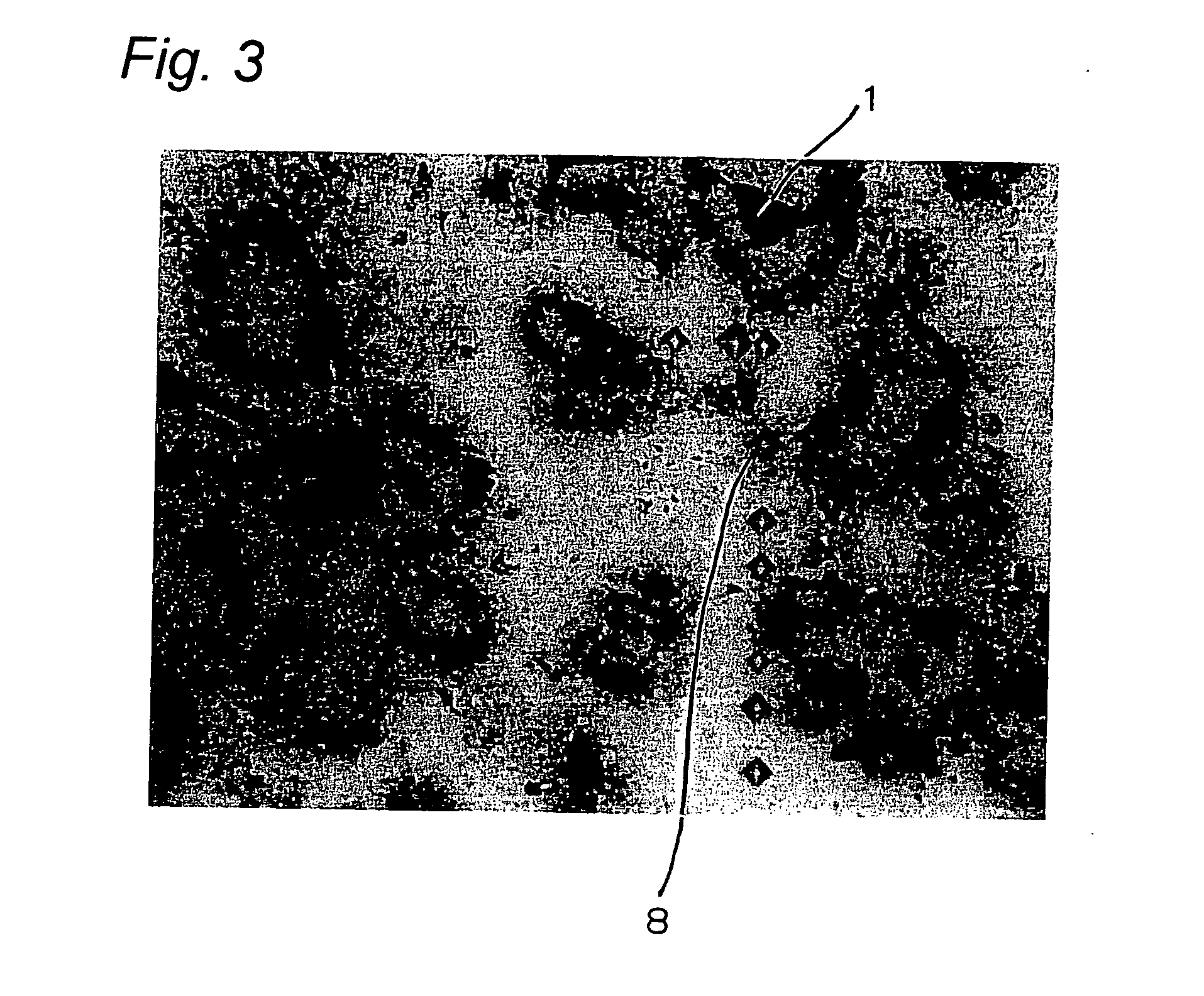
[0064] Three kinds of iron-based alloy powder were formed into a predetermined shape, and each compact so shaped was vacuum-sintered at a predetermined temperature (for example, 1180° C.) to thereby form a sintered compact, which was in turn heat-treated in a predetermined fashion, and thereafter, the surface of each compact was inspected. The materials of the samples (sintered compacts) correspond to SKH51, and the samples are hereinafter referred to as samples X, Y and Z.

[0065] Table 1 indicates results of a component analysis of samples X, Y and Z after the heat treatment.

TABLE 1unit: wt %OthersMaterialWMoCrVSiC(Fe etc.)Sample X5.5˜4.0˜3.5˜1.4˜0.4˜1.2˜≦1.06.76.05.02.40.91.8Sample Y5.5˜4.0˜3.5˜1.4˜0.4˜0.9˜≦1.06.76.05.02.40.91.4Sample Z5.5˜4.0˜3.5˜1.4˜0.4˜0.9˜≦1.06.76.05.02.40.91.4

[0066]FIG. 5 depicts heat treatment patterns conducted to the materials of the samples. Table 2 indicates the material characteristics of the samples.

TABLE 2DensityHardnessTransverse RuptureMaterial(...


PUM

PropertyMeasurementUnit
temperatureaaaaaaaaaa
porosityaaaaaaaaaa
porosityaaaaaaaaaa

Abstract

A material is shaped and sintered into a compact using iron-based alloy powder containing Cr; and a nitriding treatment having no carburizing action is conducted to the compact so that a surface of the compact may have a mixed structure 3 of an Fe—Cr—N compound layer 2, an Fe—Cr—N diffused layer, and a matrix.

Description

TECHNICAL FIELD [0001] The present invention relates to wear-resistant elements having an increased hardness by nitriding and also to a method of making the same. BACKGROUND ART [0002] A vane mounted in, for example, rotary compressors is slidably received within a vane groove defined in a cylinder. Because the vane is held in sliding contact at its side surfaces with side walls of the vane groove and at its end portion with a roller, the vane must have wear resistance. For this purpose, a material having a base material for which steel, a sintered metal or cast iron containing chromium is used and which is soft-nitrided has been proposed. This material has a first compound layer or surface layer of Fe—Cr—N and a second compound layer of the same composition formed below the first compound layer (see Document 1). [0003] Another material has been proposed having a nitrided layer that is formed by nitriding the surface of a base material of stainless steel (see Document 2). [0004] A f...

Claims


Application Information

Patent Timeline
Patent Type & Authority Applications(United States)
IPC IPC(8): C23C8/26B22F3/24C23C8/02
CPCB22F3/24C23C8/26C23C8/02B22F2003/241
Inventor FUKUHARA, HIROYUKISASAKI, KENJIHIRATA, KENSUKEHOMMA, TOSHIHIKO
Owner KAWASAKI NITRIDING
Why Eureka
Try Eureka