Implant system for Osteosynthesis

a technology of implants and osteosynthesis, applied in the field of medical devices, can solve the problems of raising the vertical profile of the installed implant, cross threading and likely a failed installation, and the alignment of the set screw with the threaded posts

Active Publication Date: 2007-03-29
SEASPINE
View PDF23 Cites 159 Cited by
  • Summary
  • Abstract
  • Description
  • Claims
  • Application Information

AI Technical Summary

Benefits of technology

[0020] In another embodiment, the upper rod holding section of an implant, whether of the hook, monoaxial or polyaxial pedicle screw type, may be provided with a flat opposed recessed sides, adjacent the bottom of the posts, with the recesses terminating at their upper ends in concave outwardly projecting shoulders. This arrangement, sometimes referred to herein as a catch basin, accommodates the use of a rod persuader having a fixed forked distal end, i.e., parallel arms, with inwardly projecting stubs adapted to slide under the shoulders to releasably secure the persuader distal end to the installed implant.

Problems solved by technology

The step of aligning the set screw with the threaded posts is a problem whether or not a separate cap is used.
Since the threads in the posts are interrupted it is difficult, particularly in light of the limited view in the surgical opening for a surgeon to ensure that the set screw is not canted with respect to the opening in the posts, resulting in cross threading and likely a failed installation.
While this arrangement solves the multiple component problem it presents another problem of raising the vertical profile of the installed implant.
The extra space required to accommodate the top of the clamp, which necessarily overlies the top of the implant posts, may result in considerable discomfort to a tall, thin patient particularly if the implant is installed in the thorax region.
In addition, the above unitary cap / screw designs do not entirely solve the screw / threaded posts alignment problem.
In addition to the separate component and alignment problems, conventional implants systems suffer another problem.
This seating step is frequently difficult due to the rigidity of the rod and the vertebra into which the implant has been installed, particularly where the vertebrae is to be moved toward the rod.
This persuader design requires that adjacent implants be at least as far apart as the transverse / offset arms at the distal end of the instrument thereby limiting its use to adjacent implants with the required spacing.
In addition, it is difficult to align and slide the offset arms into the slots.
This arrangement, like the '936 device, also limits the persuader's use on closely spaced adjacent implants.
However, tests have shown heat treatment actually increases the hardness value by only one or two points on the Rockwell C hardness scale or about 5% or less.

Method used


Image

  • Implant system for Osteosynthesis
  • Implant system for Osteosynthesis
  • Implant system for Osteosynthesis

Examples


Embodiment Construction

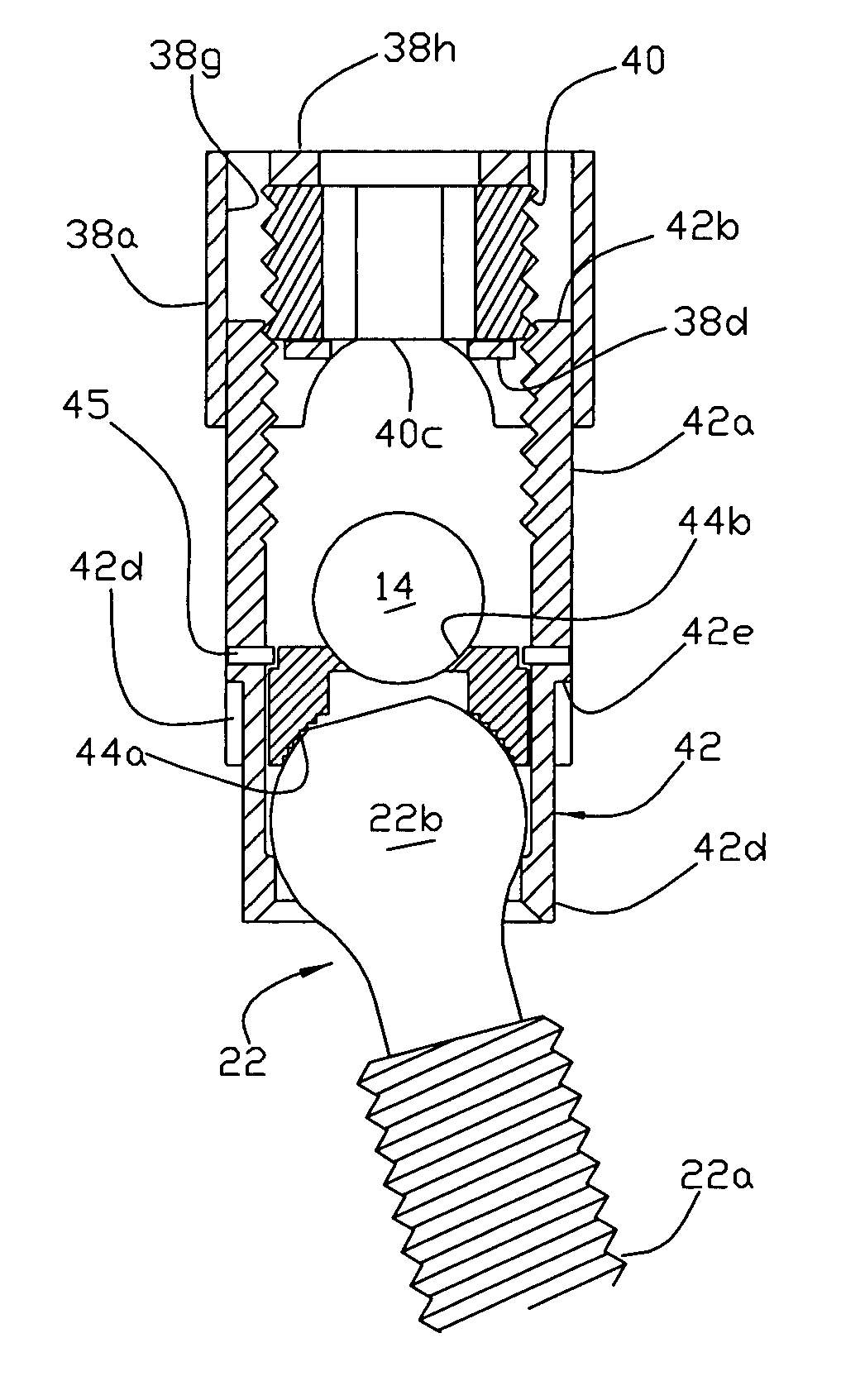
[0039] A partially completed cap 38 and a set screw 40 are illustrated in FIGS. 5a and 5b. The cap is manufactured from a high strength bio-compatible material such as titanium, e.g., by machining, a solid piece to provide opposed curved side walls 38a which are arranged to extend around and follow the outside contour of a generic implant's upstanding posts 36a (FIG. 6) leaving an open top. The implant posts have free edges 36b which are aligned parallel to the implant's longitudinal axis X1-X1. It is to be noted that the bottom section 36c of the generic implant of FIG. 7 may be of the hook, monoaxial or polyaxial type.

[0040] Flat end walls 38b of the cap extend between the side walls, as shown, and along with the side walls are arranged to encircle the implant posts. The inner surfaces 38c of the end walls are contoured to match the outer circumference of the set screw with a slight clearance, e.g., 0.0005 to 0.010″ to allow the set screw 40 to turn freely or with a slight resist...


PUM


Abstract

A anti-splay and rod securing member for use with vertebral implants of the hook, monoaxial and polyaxial types, in which a pair of arcuate upstanding internally threaded posts define a transverse opening for securing a rod to immobilize bone segments comprises an integrally formed cap and set screw with the cap having opposed curved side walls extending around the posts and flat end walls, the set screw being positioned within the posts and free to rotate within the cap so that rotation of the set screw will advance the cap and set screw in unison along the implant posts to clamp the rod and implant together. The implant may be provided with opposed catch basins for releasably securing the distal end of a rod persuasion instrument.

Description

FIELD OF THE INVENTION [0001] The present invention relates to the medical field commonly referred to as Osteosynthesis, i.e., the fusion between segments of the spine and more particularly to an implant system for use with a rod for immobilizing the segments during the fusion process. BACKGROUND OF THE INVENTION [0002] Osteosynthesis is achieved by immobilizing separate bone segments and in particular vertebral segments on either side of a failed or damaged disc. When trying to achieve osteosynthesis and specifically fusion between different segments of the spine, one has to provide some type of immobilization. There are various prior art systems which try to achieve this purpose. The different systems involve placement of implants in the form of hooks secured against the bone or pedicle screws threaded into the bone. The implants are then secured to each other by stabilizing rods or plates. [0003] A typical prior art hook implant system, illustrated in FIG. 1, includes a hook impl...

Claims


Application Information

Patent Timeline
Patent Type & Authority Applications(United States)
IPC IPC(8): A61F2/30
CPCA61B17/7032A61B17/7086A61B17/7037
Inventor CORDARO, NICHOLAS M.SMITH, COLIN M.
Owner SEASPINE
Why Eureka
Try Eureka