Trans-septal anchoring system and method

a trans-septal and anchoring technology, applied in the field of implantable medical devices, can solve the problems of increasing the risk of forming and dispersing such a clot, obtaining such data on the right side, and avoiding clot formation and dispersion

Inactive Publication Date: 2007-03-29
MEDTRONIC INC
View PDF12 Cites 25 Cited by
  • Summary
  • Abstract
  • Description
  • Claims
  • Application Information

AI Technical Summary

Problems solved by technology

As the left ventricle provides oxygenated blood throughout the body, a foreign object disposed on the left side and providing a sufficient obstruction could lead to the formation of clots and would increase the risk that such a clot would form and be dispersed.
Obtaining such data on the right side is typically non-problematic; however, obtaining the same data directly from the left side is made more difficult b

Method used


Image

  • Trans-septal anchoring system and method
  • Trans-septal anchoring system and method
  • Trans-septal anchoring system and method

Examples


Embodiment Construction

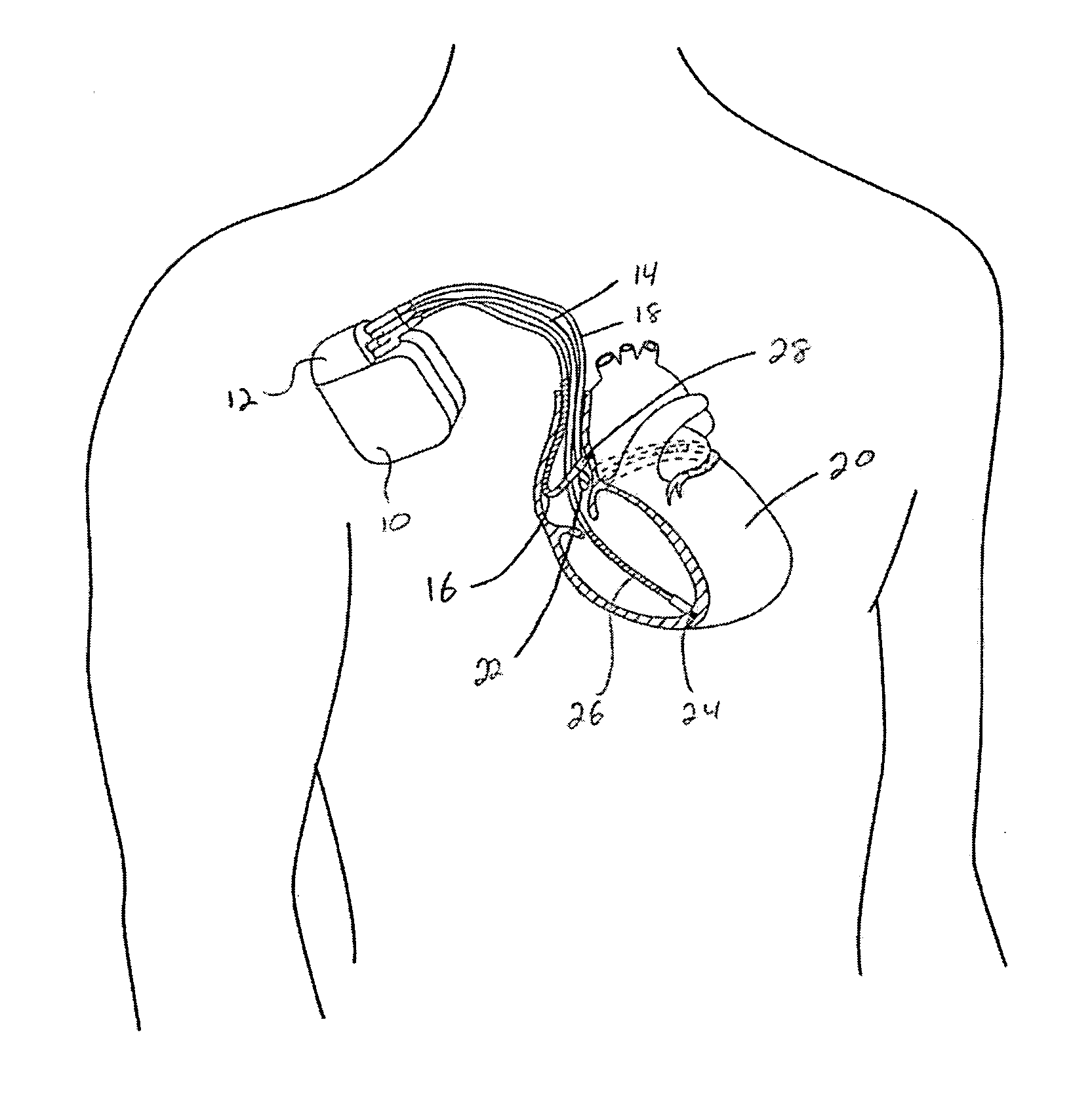
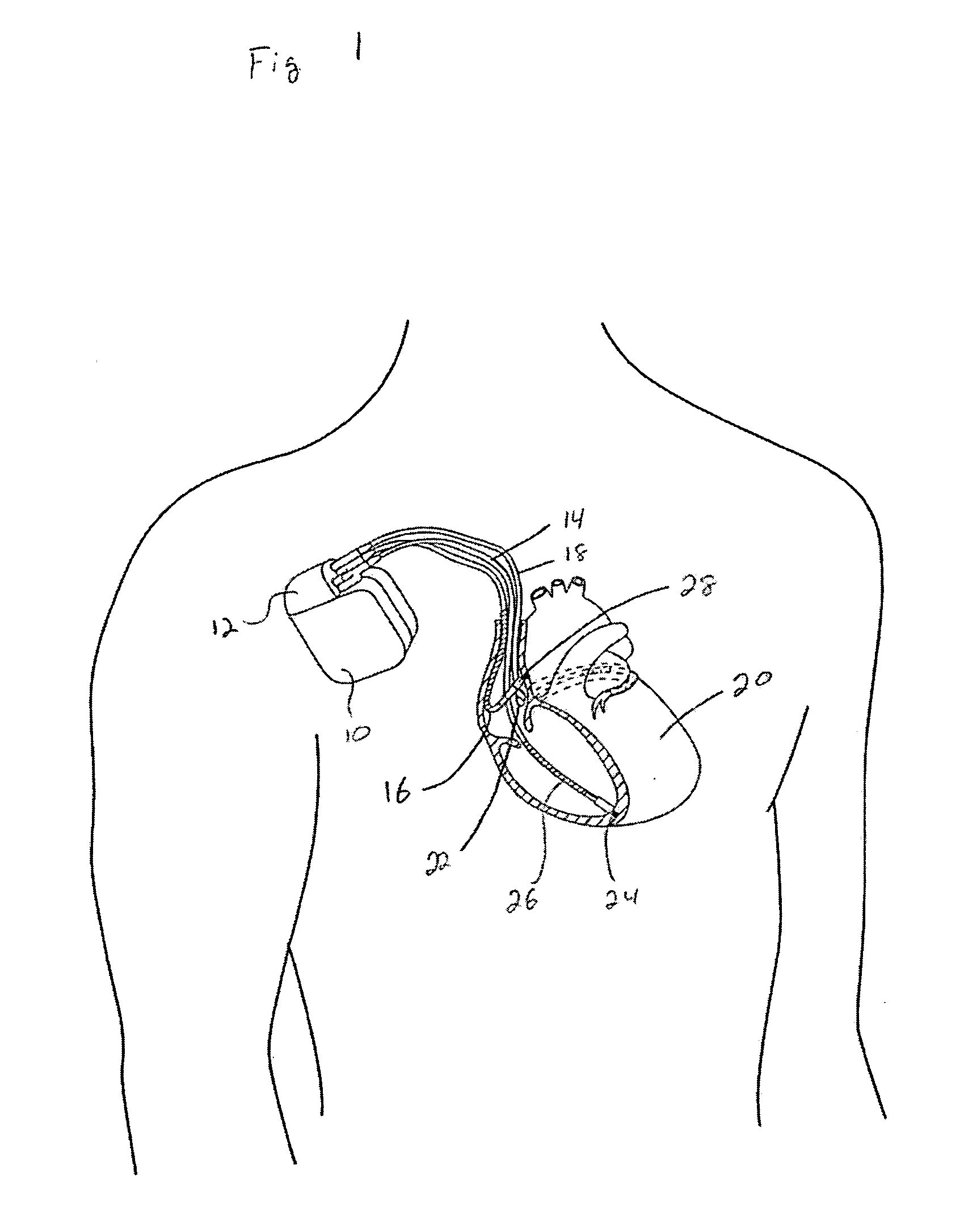
[0022]FIG. 1 illustrates an implantable medical device (IMD) 10 that includes pacing, cardioversion and defibrillation capabilities. A header block 12 forms a portion of the IMD 10 and three leads 14, 16, 18 are illustrated as coupled with the header block. A right ventricular lead 14 is disposed in the right ventricle of the heart 20. More specifically, a helical electrode tip 24 is embedded into the apex of the right ventricle. The electrode tip 24 forms or is part of a tip electrode, and a coil electrode 26 is also included. A ring electrode may be disposed between the tip electrode 24 and the coil electrode 26.

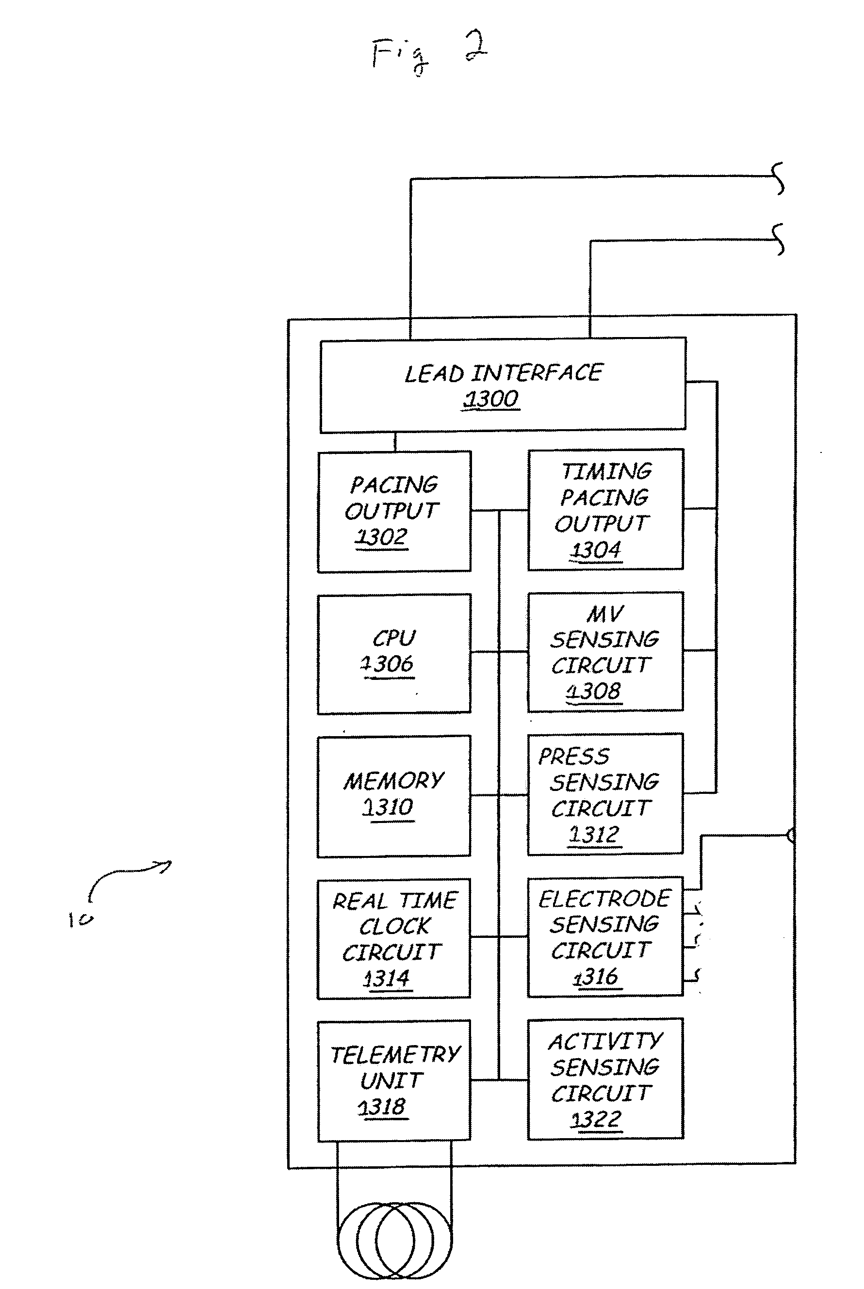
[0023] An atrial lead 16 is disposed within the right atrium such that an electrode 28 contacts an interior wall of the right atrium. A left-sided lead 18 is illustrated as passing through the coronary sinus 22 and into a cardiac vein. In this position, the left-sided lead 18 has a distal end in contact with an outer wall of the left ventricle. The IMD 10 includes a housi...


PUM


Abstract

A pressure sensor, in one embodiment, is passed through the atrial septal wall. A plurality of anchors is disposed on each side of the septal wall and secure the position of the pressure sensor.

Description

BACKGROUND OF THE INVENTION [0001] 1. Field of the Invention [0002] The present invention relates to implantable medical devices. More specifically, the present invention relates to implantable medical devices that sense or measure a cardiac parameter. [0003] 2. Description of the Related Art [0004] There are a number of implantable medical devices (IMDs) that sense various physiological parameters and / or provide a variety of therapies. For example, implantable pulse generators (IPGs) typically include one or more leads that are in contact with cardiac tissue to sense electrical depolarization and provide pacing stimuli. Implantable cardioverter / defibrillators (ICDs) also typically include one or more leads and provide a larger stimulus for cardioversion or to defibrillate the heart. Often, IMDs include both pacing and cardioversion / defibrillation capabilities. [0005] A housing containing the pulse generator, battery, capacitors, processor, memory, circuitry, etc. is implanted subcu...

Claims


Application Information

Patent Timeline
IPC IPC(8): A61N1/00
CPCA61N1/057
Inventor ZIELINSKI, TODD M.HETTRICK, DOUGLAS A.FALKNER, PHILLIP C.SEIFERT, KEVIN R.BJORKLUND, VICKI L.SCHNEIDER, MARK D.
Owner MEDTRONIC INC
Why Eureka
Try Eureka