Tire designing method and program

Inactive Publication Date: 2007-03-29
YOKOHAMA RUBBER CO LTD
View PDF5 Cites 9 Cited by
  • Summary
  • Abstract
  • Description
  • Claims
  • Application Information

AI Technical Summary

Benefits of technology

[0020] Furthermore, the present invention provides a program executable by a computer, for predicting a change with time caused by use of a pneumatic tire to allow the computer to design a tire, the program including: a model preparing procedure of allowing computing means of a computer to tentatively select at least one of a tire profile shape, a shape of a tire component member and a physical property data of the tire component member as a parameter and to prepare an initial tire model representing the pneumatic tire by using a finite number of elements; an inner pressure filling processing procedure of allowing the computing means to perform a calculation of a first inner pressure filling processing performed on the prepared initial tire model; a time-varying change predicting procedure of allowing the computing means to modify at least one of a stress acting on the initial tire model by first the inner pressure filling processing and the physical property data used for the initial tire model corresponding to a predetermined measure of elapsed time to deform the initial tire model and to predict a tire profile shape after a change with time by using the deformed initial tire model; a margin of safety calculating procedure of allowing the comput

Problems solved by technology

Moreover, even if the tire property is good in the initial state, the tire property is sometimes greatly degraded with use.
In particular, the durability is greatly affected by the tire profile shape that constantly changes with the use of the tire.
In conventional techniques including the above-mentioned Patent Documents, however,

Method used


Image

  • Tire designing method and program
  • Tire designing method and program
  • Tire designing method and program

Examples


Embodiment Construction

[0029] Hereinafter, a tire designing method and a program executable by a computer executing the method according to the present invention will be described in detail based on the preferred embodiments illustrated in the accompanying drawings.

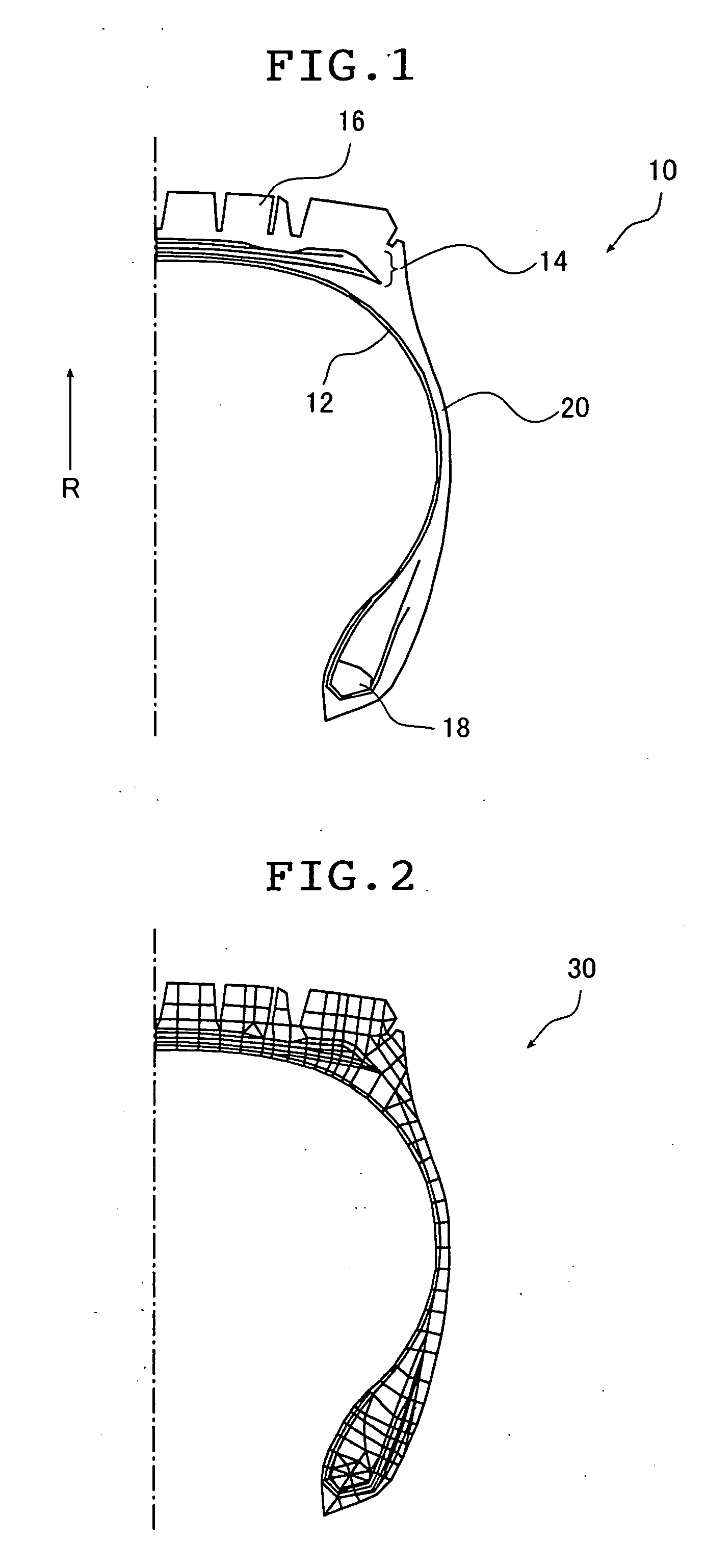
[0030]FIG. 1 shows an example of a structure of a sectional shape (a tire profile shape) of a heavy-duty tire (track / bus tire).

[0031] A pneumatic tire (hereinafter, referred to as tire) 10 mainly includes as tire component members: a carcass member 12; a belt member 14; a tread member 16; a bead member 18; and a side member 20.

[0032] The carcass member 12 is a tire frame obtained by coating a cord material such as a steel cord with a rubber material, whereas the belt member 14 is a tire frame that prevents the carcass member 12 from being expanded in a radial direction R while fastening it. The tread member 16 is a rubber member provided on the outer side of the belt member 14 in the radial direction, on which a tread pattern is formed comin...


PUM


Abstract

In a tire designing method, at least one of a tire profile shape, a shape of a tire component member and physical property data of the tire component member is tentatively selected as a parameter to prepare an initial tire model (30) representing the pneumatic tire by using a finite number of elements, and at least one of a stress acting on the initial tire model by the inner pressure filling processing and the physical property data used for the initial tire model is modified corresponding to a predetermined measure of elapsed time, to thereby deform the initial tire model and a tire profile shape after a change with time is predicted by using the deformed initial tire model. By preparing the tire model (30) with the predicted tire profile shape and applying the inner pressure filling processing and road contact processing thereto, the maximum principal strains in the elements of the tire model (30) are calculated, and the margins of safety of the tire component members are calculated by using the maximum principal strains. The tentatively selection is repeated until the calculated margins are equal to or larger than a pre-set reference margin of safety so that a tire with excellent durability can be designed.

Description

TECHNICAL FIELD [0001] The present invention relates to a tire designing method of predicting a change with time, which is caused by the use of a pneumatic tire, by using a tire model to design a tire and to a program for executing the designing method. More particularly, the present invention relates to a tire designing method of efficiently determining parameters such as a tire profile shape, a shape of a tire component member and a physical property data of the tire component member when a pneumatic tire excellent in tire durability is to be designed and to a program for executing the designing method. BACKGROUND ART [0002] In these days, various methods of using a finite element (FE) model obtained by dividing a pneumatic tire (hereinafter, referred to as tire) into a plurality of finite elements to predict tire properties including tire durability for designing a tire based on the predicted tire properties have been proposed. [0003] Any of those methods uses a computer to prepa...

Claims


Application Information

Patent Timeline
IPC IPC(8): G05D1/00G01M17/00B60C19/00G06F17/50
CPCB60C19/00B60C99/006G06F17/5095G06F30/15
Inventor KABE KAZUYUKIRACHI KEITA
Owner YOKOHAMA RUBBER CO LTD
Why Eureka
Try Eureka