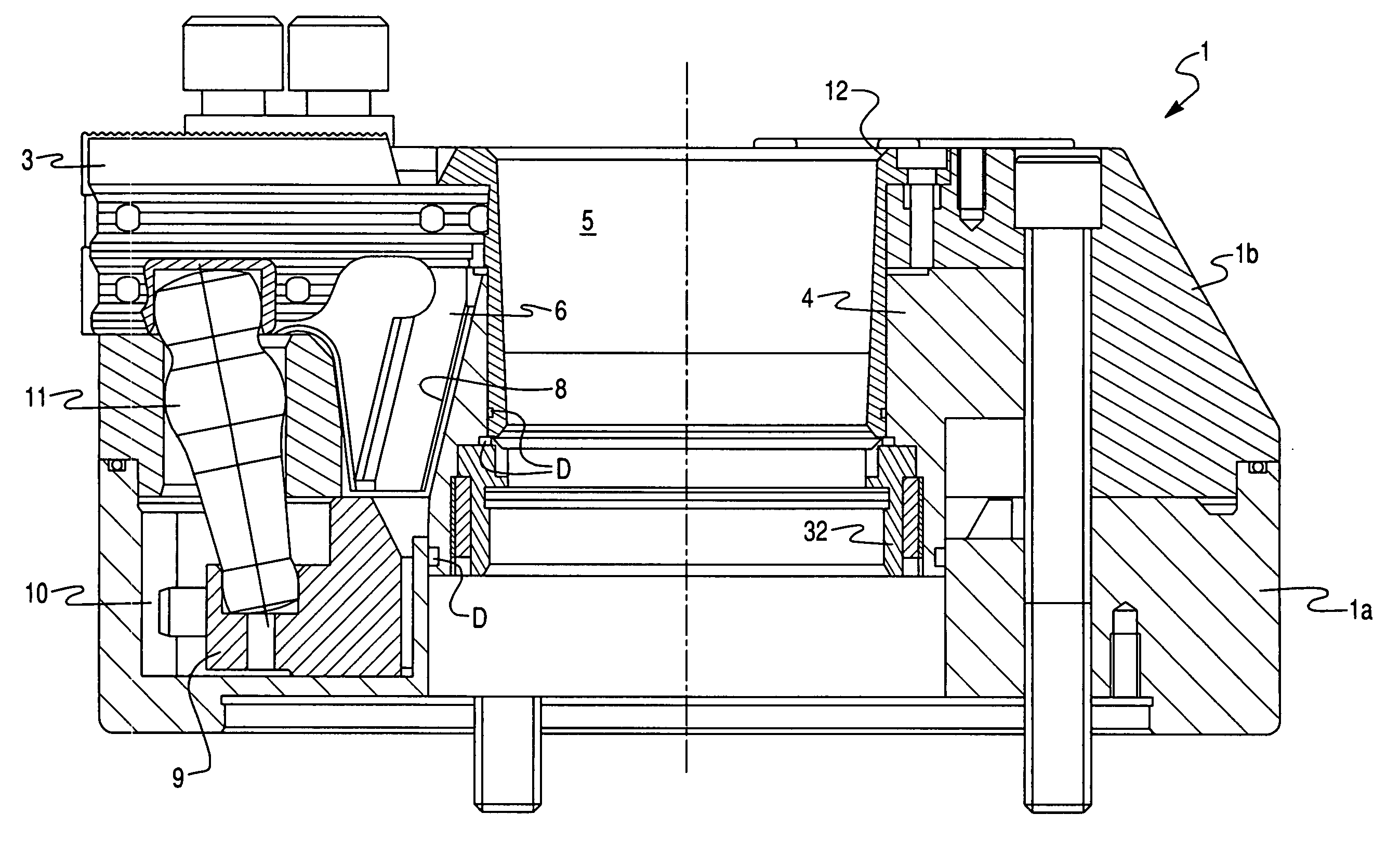
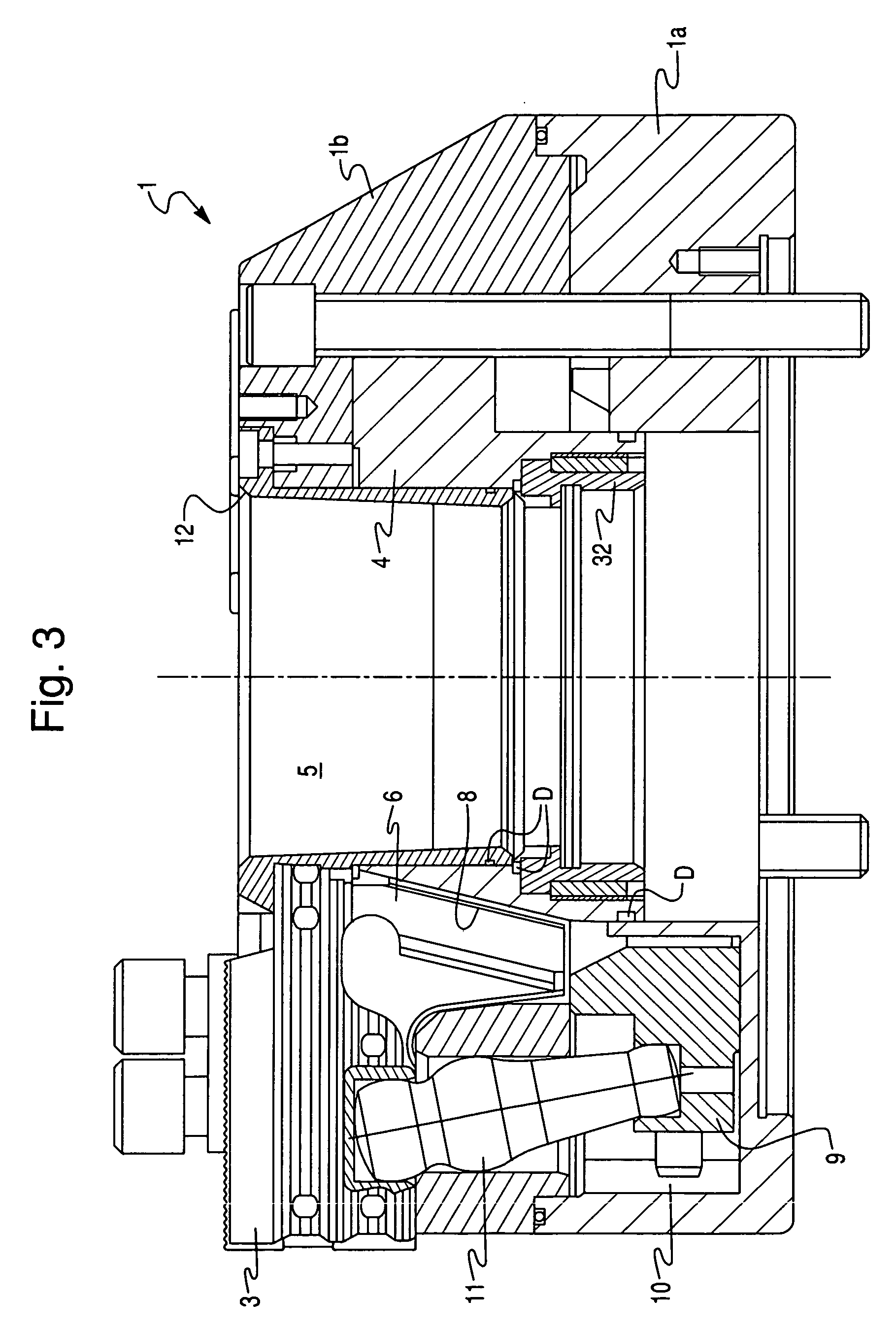
[0008] This object is achieved, according to the present invention, in that there is provided in each pocket at least one pump piston that is arranged in a cylinder bore of the conveying element that is movable in the pocket, forming a piston space located therebetween, and is held in the pocket in such a way that the conveying element, in the context of its radial motions, moves relative to the pump piston while making the piston space smaller and larger; that the pump piston protrudes, with a radially outer, tubular end portion, through the conveying element and projects into the radially outer region of the pocket, the tubular end portion being connected via a connecting conduit to the piston space; that a first nonreturn valve, which permits a fluid flow from the pocket through the tubular end portion and the connecting conduit into the piston space but blocks a lubricant flow in the opposite direction, is provided in the pump piston; and that the piston space is connected to a lubricating orifice of the chuck body through an outlet conduit embodied in the conveying element, and a second nonreturn valve is provided which allows a lubricant flow from the piston chamber to the lubricant conduit but prevents a
backflow of lubricant in the opposite direction.
[0009] The invention is thus based on the idea of providing a pump
system in order to assist the conveyance of lubricant out of the pockets to the sliding surfaces that are to be lubricated, which conveyance is brought about primarily by the displacement effect of the conveying element moving outward in the pocket. The pump
system is constituted substantially by a pump piston that, in particular, is held in fixed fashion on the radially inner pocket wall and engages into the cylinder bore of the conveying element to form a piston space. When the conveying element is moved radially outward, this
radial motion takes place relative to the stationary pump piston, so that the piston space becomes larger and a negative pressure is correspondingly established in it, with the consequence that lubricant is aspirated out of the pocket through the tubular end portion of the pump piston and into the piston space. The second nonreturn valve prevents lubricant or air from also being aspirated out of the lubricating orifices of the chuck body. When the conveying element is moved radially inward, this causes the piston space to become smaller, with the result that the lubricant present therein is pushed into the lubricating orifices and through them to the sliding surfaces that are to be lubricated. The first nonreturn valve prevents a
backflow of lubricant into the pocket as it becomes larger. The result is that satisfactory
lubrication is ensured even when the pockets are not completely filled with lubricant.
[0010] A further
advantage is that the position of the aspiration opening of the tubular end portion of the pump piston is independent of the position of the conveying element in the pocket. Because the pump piston does not move, the inlet end of the pump piston can extend as far as the outer wall of the pocket, i.e. into a region in which sufficient lubricant is still present even if the pocket is only partially filled.
[0013] According to an embodiment of the invention, provision is made for the pump piston to be pressed against the radially inner wall of the pocket by a
helical compression spring that is arranged in the piston space and is braced between the pump piston and the conveyer. This ensures, in simple fashion, that the pump piston is held against the inner wall of the pocket.
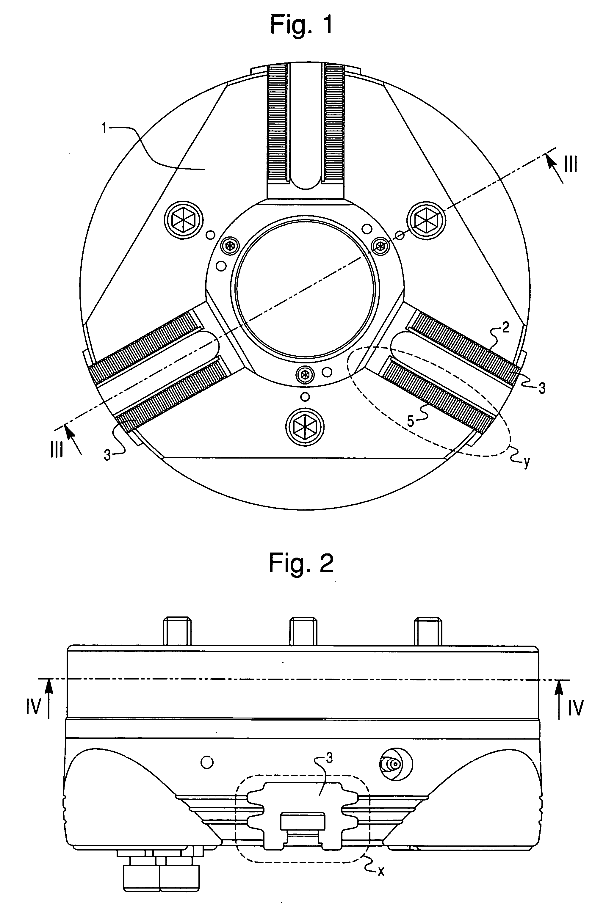
[0016] According to a preferred embodiment of the invention, provision is made for two pump pistons to be arranged in each pocket, symmetrically with respect to the center axis of the conveying element. This configuration has the
advantage that imbalances are avoided, and moreover that in the case in which the conveying elements are embodied as
centrifugal force compensation weights, the pump systems do not collide with the lever by way of which the centrifugal force compensation weight is coupled to the associated clamping jaw. It is moreover possible, by way of the two pump systems, to supply lubricant to two corresponding sliding surfaces concurrently with one another.
[0018] A protective
bushing, which is embodied to diverge conically toward the front side of the chuck body, can furthermore be inserted into the central receptacle of the clamping chuck. Cooling water dripping onto this
conical surface is conveyed axially forward to the chuck face by way of the gradient resulting from the conicity, in combination with the centrifugal force of the rotary motion. A majority of the
dirt particles present in the water can thereby be floated out again toward the front. Seals can furthermore be provided in order to prevent any entry of
cooling fluid into the chuck body from the region of the receptacle, and thereby to prevent washouts.
