Supercharge Your Innovation With Domain-Expert AI Agents!

Clamping chuck

a technology of chuck and chuck body, which is applied in the field of chuck, can solve the problems of reducing the clamping force, risk, and insufficient pumping action resulting from the motion of centrifugal force compensation weight, and achieve satisfactory lubrication and prevent the backflow of lubrican

Inactive Publication Date: 2010-07-27
SCHUNK GMBH & CO KG
View PDF17 Cites 3 Cited by
  • Summary
  • Abstract
  • Description
  • Claims
  • Application Information

AI Technical Summary

Benefits of technology

This solution ensures consistent and reliable lubrication even when pockets are not fully filled, preventing backflow and maintaining effective clamping force at high speeds by utilizing the pump system's displacement effect to deliver lubricant to the necessary areas.

Problems solved by technology

One problem that often occurs in conventional clamping chucks is that with increasing circumferential velocity, large centrifugal forces occur which cause the inherently preloaded clamping jaws to be pulled outward, thus resulting in a decrease in clamping force.
A disadvantage of this known approach is that the pumping action resulting from the motion of the centrifugal force compensation weights is not sufficient if the pockets are only partly filled with lubricating grease; and the risk also exists that some of the lubricant contained in the lubricant conduits will be aspirated back into the pocket in the context of an inwardly-directed motion of the centrifugal force compensation weights.

Method used


Image

  • Clamping chuck
  • Clamping chuck
  • Clamping chuck

Examples


Embodiment Construction

)

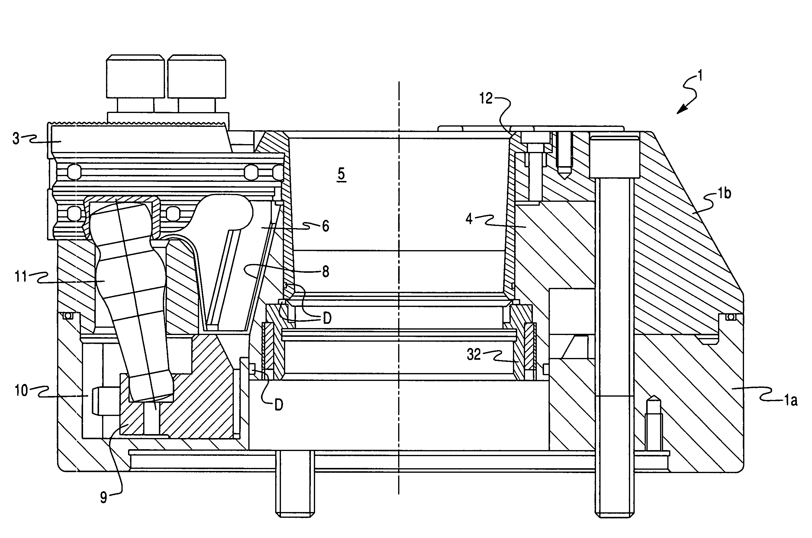
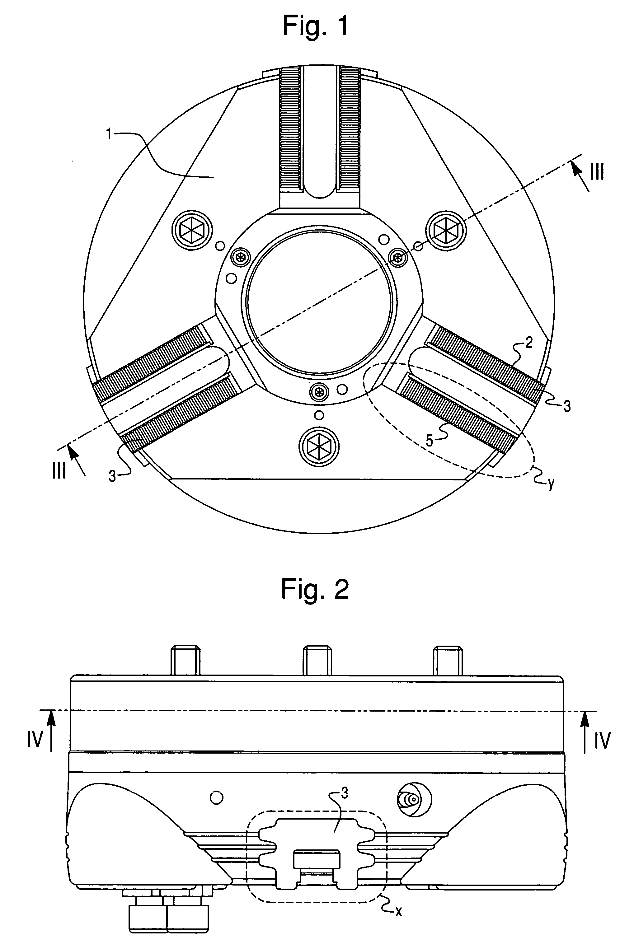
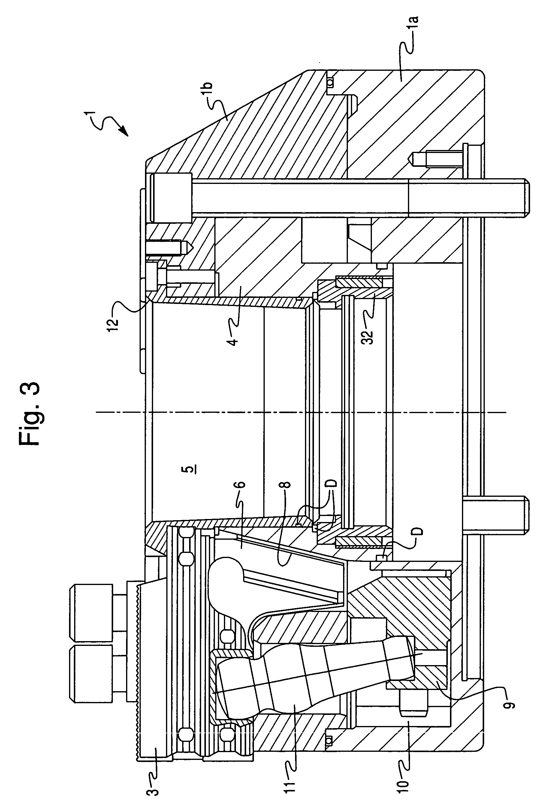
[0031]The Figures depict a powered clamping chuck according to the present invention that can be used, for example, to clamp workpieces on lathes. Part of the clamping chuck is a chuck body 1, which is divided axially into a base body 1a and a cover 1b and possesses a basically cylindrical shape, and which can be bolted onto the spindle (not depicted) of, for example, a lathe. Provided in the one, front end face of chuck body 1 are radial jaw guides 2 that are evenly distributed over the circumference, i.e. arranged at a respective 120° offset from one another. Inserted into jaw guides 2 are clamping jaws 3 that are each made up of a base jaw and an attachable jaw threadable thereonto, only the base jaw being depicted in the drawings. To allow absorption of the forces that occur when clamping workpieces for machining, guide rails 3a, and guide grooves 2a engaged therewith, are embodied respectively on the lateral surfaces of clamping jaws 3 and of jaw guides 2. Concretely, two guid...


PUM


Abstract

A clamping chuck has a chuck body and clamping jaws that are shiftable in radial jaw guides. Conveying elements are radially guided in the chuck body. Lubricant is pumped into lubricating orifices, and through them to lubrication points by radial motion of the conveying elements. Each pocket has at least one pump piston in a cylinder bore of the conveying element, and is held in the pocket in so that the conveying element moves relative to the pump piston. The pump piston protrudes through the conveying element and into the radially outer region of the pocket. The tubular end portion is connected to the piston space. A first nonreturn valve is provided in the pump piston. The piston space is connected to a lubricating orifice of the chuck body, and a second nonreturn valve allows lubricant flow from the piston chamber to the lubricant conduit.

Description

CROSS-REFERENCE TO RELATED APPLICATIONS AND CLAIM TO PRIORITY[0001]This application is related to patent application number 041 518.0-14, filed Aug. 31, 2006, in the Federal Republic of Germany, the disclosure of which is incorporated by reference and to which priority is claimed.FIELD OF THE INVENTION[0002]The present invention relates to a clamping chuck, having a chuck body and clamping jaws that are arranged shiftably in radial jaw guides of the chuck body, pockets in which conveying elements are guided in radially movable fashion being embodied in the chuck body, and means being provided for pumping lubricant that collects in the pockets into lubricating orifices, and through the latter to desired lubrication points, by way of the radial motion of the conveying elements.BACKGROUND OF THE INVENTION[0003]Clamping chucks of this kind are known, for example, from DE 38 22 506 C1, and in practice are used chiefly to clamp workpieces onto lathes for machining. Conventional clamping c...

Claims


Application Information

Patent Timeline
Patent Type & Authority Patents(United States)
IPC IPC(8): B23B31/14B23B31/177B23B31/16
CPCB23B31/14B23B31/16266Y10T279/19Y10T279/1973Y10T279/243B23B2250/12B23B31/141
Inventor GROSS, JOHANN
Owner SCHUNK GMBH & CO KG
Features
  • R&D
  • Intellectual Property
  • Life Sciences
  • Materials
  • Tech Scout
  • Unparalleled Data Quality
  • Higher Quality Content
  • 60% Fewer Hallucinations
Learn More