Supercharge Your Innovation With Domain-Expert AI Agents!

General-purpose engine

a general-purpose, engine-type technology, applied in the direction of pressure lubrication, lubricant level maintenance, lubrication elements, etc., can solve the problems of affecting the lubrication of engine parts, insufficient oil spray, and large reduction of the amount of reserved oil in the crank chamber, so as to keep engine parts lubricated.

Active Publication Date: 2017-03-28
HONDA MOTOR CO LTD
View PDF9 Cites 2 Cited by
  • Summary
  • Abstract
  • Description
  • Claims
  • Application Information

AI Technical Summary

Benefits of technology

The present invention provides a general-purpose engine that can maintain the amount of oil reserved in the crank chamber and keep engine parts lubricated without hindrance. It achieves this by using an unidirectional valve to push back oil from the valve operating chamber to the crank chamber via the lower oil passage when the engine is inclined. The unidirectional valve is easily attachable without major alterations to a conventional engine and uses a gasket to minimize improvement costs. The stem portion of the valve body is designed to prevent damage due to its contact with the inner peripheral surface of the valve attachment hole. The through-holes for allowing passage of the positive pressures also serve as the holes with which the positioning claws engage, simplifying the structure. The ease of installation of the unidirectional valve is also enhanced.

Problems solved by technology

In this case, it is likely that: a large amount of oil reserved in a crank chamber flows into a valve operating chamber via a lower oil passage; thereby, the amount of oil reserved in the crank chamber decreases to a large extent, and oil spray generating means insufficiently generates oil spray; and lubrication of engine parts is hindered.

Method used


Image

  • General-purpose engine
  • General-purpose engine
  • General-purpose engine

Examples


Embodiment Construction

[0020]Descriptions will be hereinbelow provided for an embodiment of the present invention on the basis of the accompanying drawings.

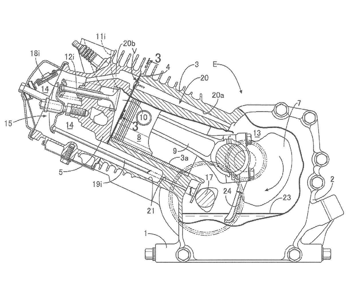
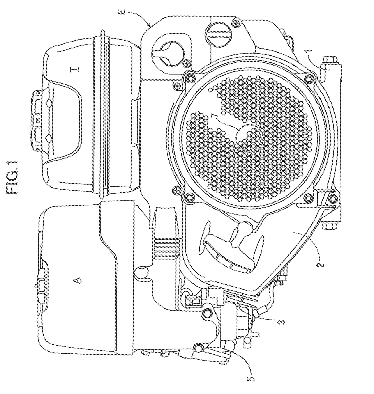
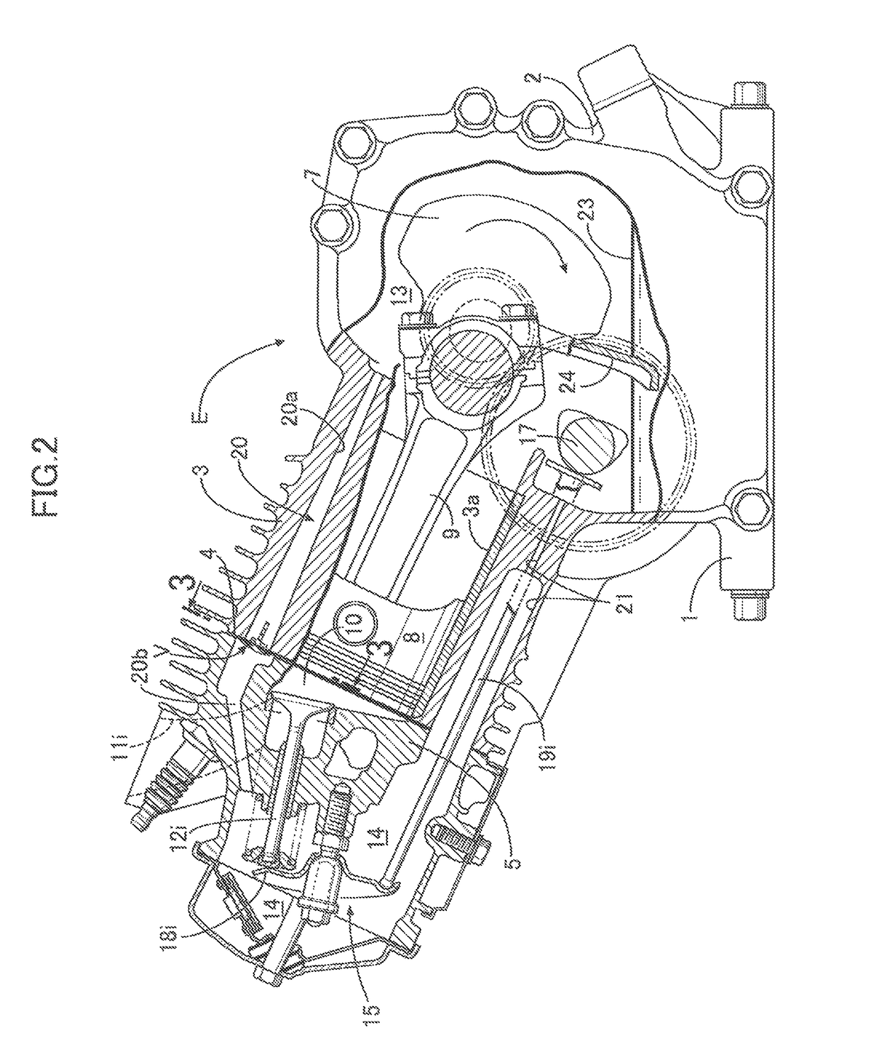
[0021]In FIGS. 1 and 2, a general-purpose engine E includes: a crank case 2 having a mounting flange 1 in its bottom portion; a cylinder block 3 extending obliquely from one side of the crank case 2; and a cylinder head 5 connected to an end surface of the cylinder block 3 via a gasket 4. A fuel tank T and an air cleaner A are attached to upper portions of the crank case 2 and the cylinder block 3, respectively. The mounting flange 1 is mounted on a work machine which uses the general-purpose engine E as a driving source.

[0022]A crank shaft 7 is disposed in a crank chamber 13 inside the crank case 2. The crank shaft 7 is linked, via a connecting rod 9, to a piston 8 which is fitted in a cylinder bore 3a of the cylinder block 3. In addition, a combustion chamber 10 continuing to the cylinder bore 3a, as well as an intake port 11i and an exhaust port (no...


PUM


Abstract

In a general-purpose engine including a cylinder block extending obliquely from one side of a crank case, and a cylinder head connected to an end surface of the cylinder block via a gasket, a unidirectional valve for allowing a flow of a fluid from a crank chamber to a valve operating chamber and blocking a reverse flow of the fluid is installed in an upper oil passage. In a case where lubricant oil reserved in the crank chamber flows into the valve operating chamber via a lower oil passage when the engine inclines such that the inclined cylinder block further slants, positive pressures transmitted from the crank chamber to the valve operating chamber push the oil, which once flows into the valve operating chamber, back to the crank chamber via the lower oil passage.

Description

BACKGROUND OF THE INVENTION[0001]Field of the Invention[0002]The present invention relates to an improvement of a general-purpose engine used for power of various work machines such as a lawn mower and the like, particularly, a general-purpose engine comprising: a crank case having a mounting flange in a bottom portion of the crank case; a cylinder block extending obliquely from one side of the crank case; and a cylinder head connected to an end surface of the cylinder block via a gasket, in which a crank chamber in the crank case includes oil spray generating means for generating oil spray for lubricating engine parts by scattering lubricant oil reserved in the crank chamber, and upper and lower side portions of the cylinder block and the cylinder head are provided respectively with an upper oil passage and a lower oil passage which communicate the crank chamber and a valve operating chamber in the cylinder head with each other.[0003]Description of the Related Art[0004]Such a gener...

Claims


Application Information

Patent Timeline
Patent Type & Authority Patents(United States)
IPC IPC(8): F02B75/00F01M11/00F01M11/06F01M9/12F01M1/04F01M9/10F01M11/02F01M9/06
CPCF01M11/02F01M1/04F01M9/06F01M9/105F01M9/12F01M11/0004F01M11/062F01M2011/0033F01M2011/021
Inventor ISHIKAWA, TAKESHI
Owner HONDA MOTOR CO LTD
Features
  • R&D
  • Intellectual Property
  • Life Sciences
  • Materials
  • Tech Scout
  • Unparalleled Data Quality
  • Higher Quality Content
  • 60% Fewer Hallucinations
Learn More