Supercharge Your Innovation With Domain-Expert AI Agents!

Adjustment unit for azimuth adjustment and/or pitch adjustment of a wind turbine, and method

a technology for wind turbines and adjustment units, which is applied in the direction of machines/engines, mechanical equipment, and gearwheels. it can solve the problems of gearwheels of this type, wear of gearwheels that are arranged in the region of wear, and the inability to adjust the azimuth and/or pitch of wind turbines, so as to reduce the failure probability of wind turbines or eliminate one.

Active Publication Date: 2021-08-17
WOBBEN PROPERTIES GMBH
View PDF24 Cites 0 Cited by
  • Summary
  • Abstract
  • Description
  • Claims
  • Application Information

AI Technical Summary

Benefits of technology

The solution provides a robust and low-maintenance adjustment mechanism with a high transmission ratio, reducing the risk of tooth fracture and wear, and increasing the reliability and efficiency of wind turbine operations by distributing loads evenly across multiple cam sections.

Problems solved by technology

In particular in the case of the rotational connections which are known for wind turbines, in particular in the area of the pitch drive and / or the azimuth drive, the wear of the gearwheel arrangement does not as a rule occur uniformly.
As a consequence, the wear is particularly great on teeth which are arranged in said region.
Furthermore, gearwheel arrangements of this type have the disadvantage that they can fail suddenly, for example, as a result of a tooth fracture.
Furthermore, the shock loading of a gearwheel connection of this type is restricted.
Gearwheel connections which are currently being used have an increased failure probability, which results in the fact that the wind turbine has a limited availability.
Furthermore, the large overall sizes of the spur gear toothing systems which are as a rule used result in further high costs.

Method used


Image

  • Adjustment unit for azimuth adjustment and/or pitch adjustment of a wind turbine, and method
  • Adjustment unit for azimuth adjustment and/or pitch adjustment of a wind turbine, and method
  • Adjustment unit for azimuth adjustment and/or pitch adjustment of a wind turbine, and method

Examples


Embodiment Construction

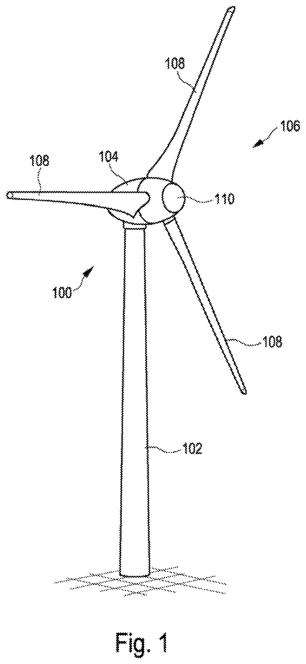
[0069]FIG. 1 shows a diagrammatic, three-dimensional view of one exemplary embodiment of a wind turbine. FIG. 1 shows, in particular, a wind turbine 100 with a tower 102 and a nacelle 104. A rotor 106 with three rotor blades 108 and a spinner 110 is arranged on the nacelle 104. During operation, the rotor 106 is set in a rotational movement by way of the wind and, as a result, drives a generator on the nacelle 104. Furthermore, the wind turbine 100 has an adjustment unit in the nacelle 104 at the connecting point between the tower 102 and a motor casing, which adjustment unit makes the rotation of the nacelle 104 with the rotor 106 possible in a horizontal plane without the use of a spur gear mechanism, by an adjustment unit according to the invention being provided. Moreover, the rotor 106 has in each case an adjustment unit according to the invention at the connecting point between a hub and the rotor blades 108.

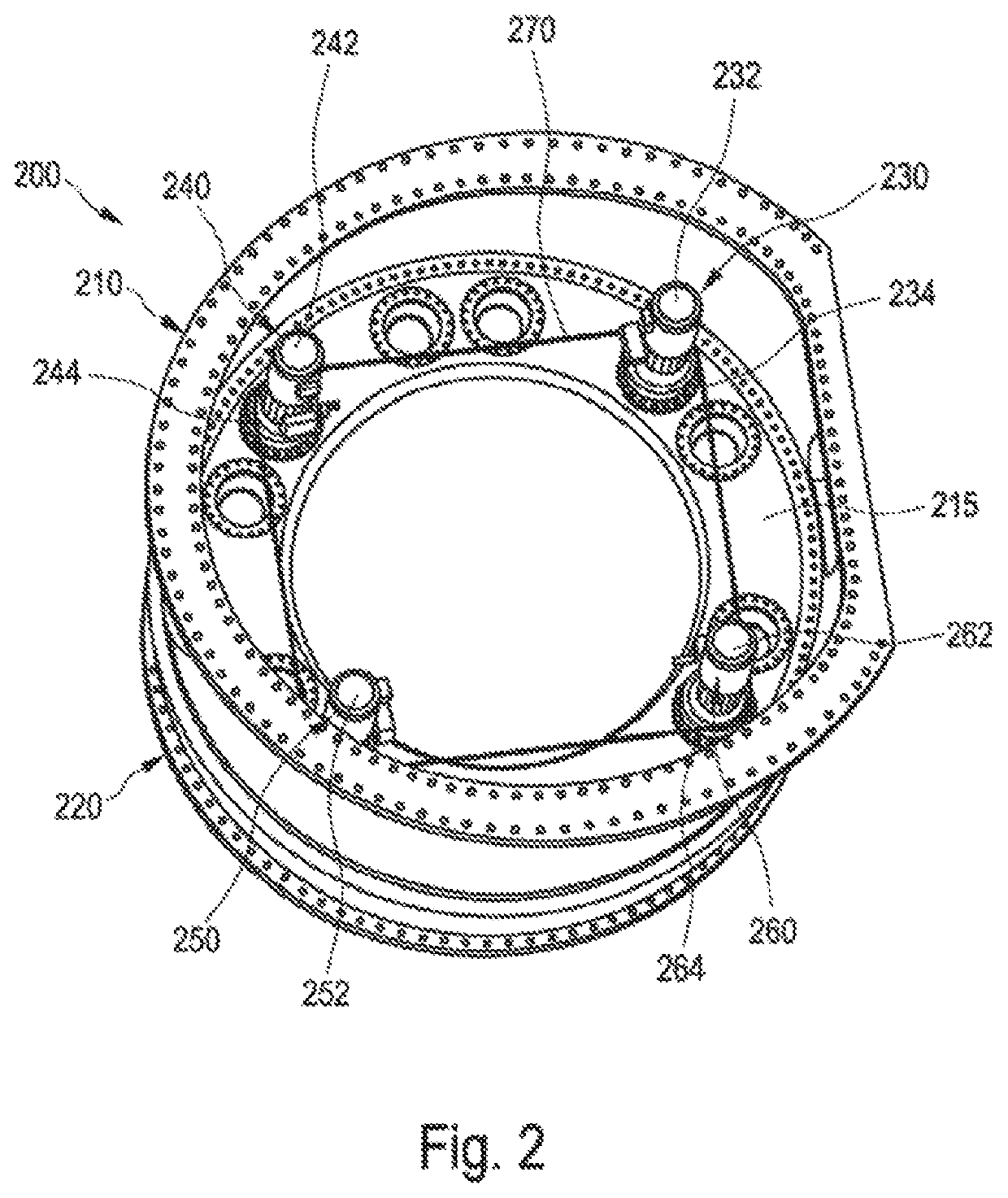
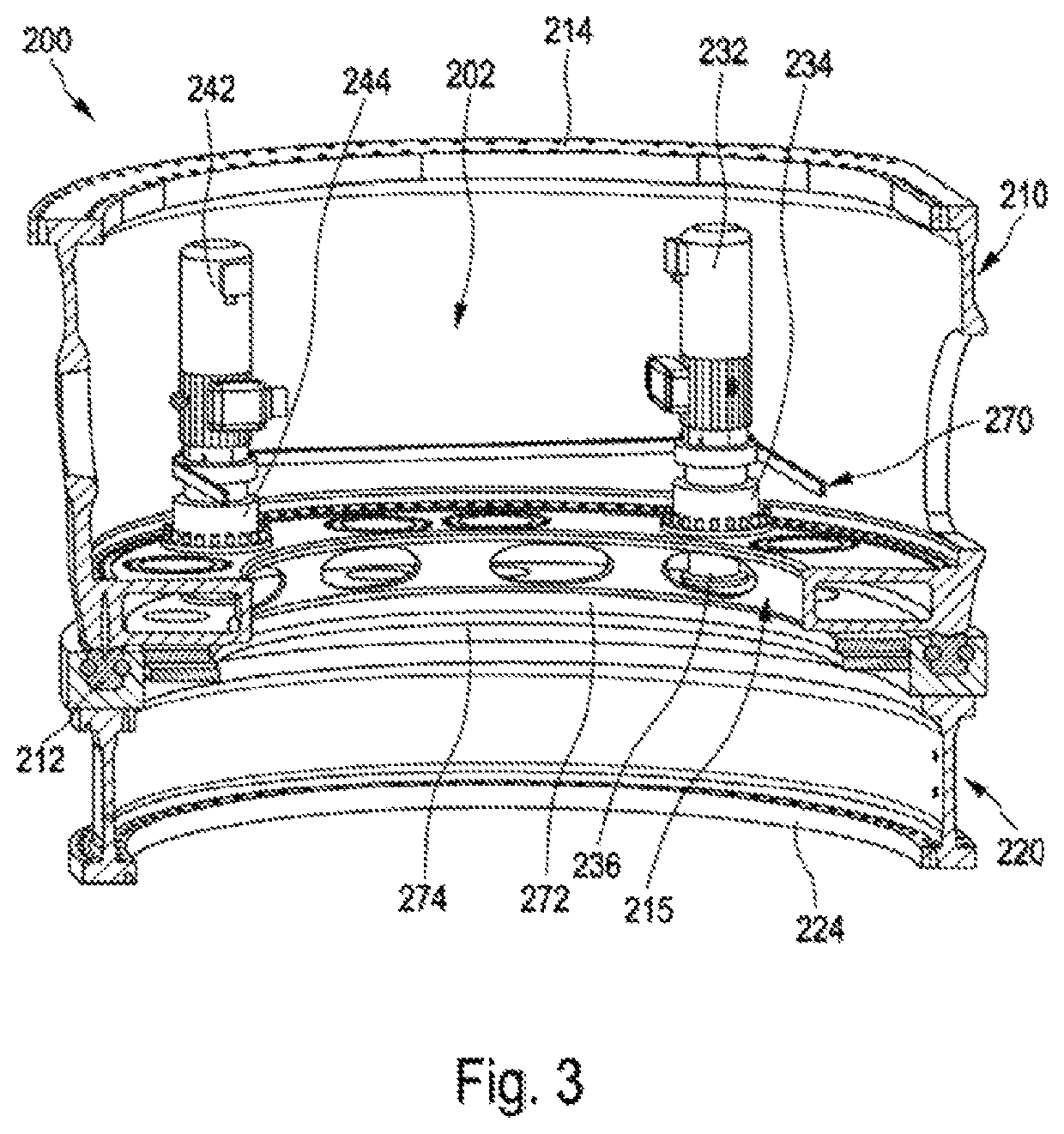
[0070]FIGS. 2-5 relate, in particular, to adjustment units of this ty...


PUM


Abstract

A adjustment unit for an azimuth adjustment and / or for a pitch adjustment of a wind turbine, to an adjustment apparatus, to a pitch adjustment apparatus, to an azimuth adjustment apparatus, to a wind turbine, and to methods for the rotor blade adjustment and wind direction tracking, and to the use of an adjustment unit and / or adjustment apparatus. The adjustment unit for an azimuth adjustment and / or for a pitch adjustment of a wind turbine comprises a drive unit which can be arranged on a first annular flange and has an eccentric shaft, a first engagement element which can be arranged on a circumference of a second annular flange which is arranged such that it can be rotated with respect to the first annular flange, a multiplicity of concavely and convexly configured first cam sections being arranged on a circumferential face of the first engagement element, and a second engagement element, with concave and convex second cam sections which are arranged on a circumferential face and correspond to the first cam sections.

Description

BACKGROUNDTechnical Field[0001]The invention relates to an adjustment unit for an azimuth adjustment and / or for a pitch adjustment of a wind turbine, to an adjustment apparatus, to a pitch adjustment apparatus, to an azimuth adjustment apparatus, to a wind turbine, and to methods for the rotor blade adjustment and wind direction tracking, and to the use of an adjustment unit and / or an adjustment apparatus.Description of the Related Art[0002]Wind turbines are generally known. The prevailing design of wind turbines is currently the three-bladed horizontal axis wind turbine, in the case of which the rotor is situated on the windward side during operation and the motor casing of which is arranged on the tower, and the wind direction is tracked actively, in particular by way of an azimuth adjustment unit. Furthermore, it is customary that the rotor blades can be rotated about a longitudinal axis by means of a pitch adjustment unit. The use of gearwheel arrangements for rotational connect...

Claims


Application Information

Patent Timeline
Patent Type & Authority Patents(United States)
IPC IPC(8): F03D7/02F03D80/70F03D80/50F03D1/06
CPCF03D7/0224F03D80/70F03D1/0658F03D7/0204F03D80/50F05B2260/79F16C2360/31F16H1/32F05B2260/403F05B2260/4031F05B2260/503F05B2260/504F05B2260/506F05B2260/76F03D80/00Y02E10/72F16H25/02
Inventor GUDEWER, WILKOJEPSEN, TORSTEN
Owner WOBBEN PROPERTIES GMBH
Features
  • R&D
  • Intellectual Property
  • Life Sciences
  • Materials
  • Tech Scout
  • Unparalleled Data Quality
  • Higher Quality Content
  • 60% Fewer Hallucinations
Learn More