Labyrinthine end disk rotor

Inactive Publication Date: 2007-04-05
RELIANCE ELECTRIC TECH
View PDF0 Cites 24 Cited by
  • Summary
  • Abstract
  • Description
  • Claims
  • Application Information

AI Technical Summary

Benefits of technology

[0007] There exists a need, therefore, for a method and

Problems solved by technology

For example, if not properly accounted for, the centripetal force in the end ring may cause plastic deformation of the end ring, which can lead to an unbalanced rotor that prematurely malfunctions.
Further, at higher speeds, the rotational forces may cause a traditional end ring to peel away from the lamination stack or, in the case of a porous

Method used


Image

  • Labyrinthine end disk rotor
  • Labyrinthine end disk rotor
  • Labyrinthine end disk rotor

Examples


Embodiment Construction

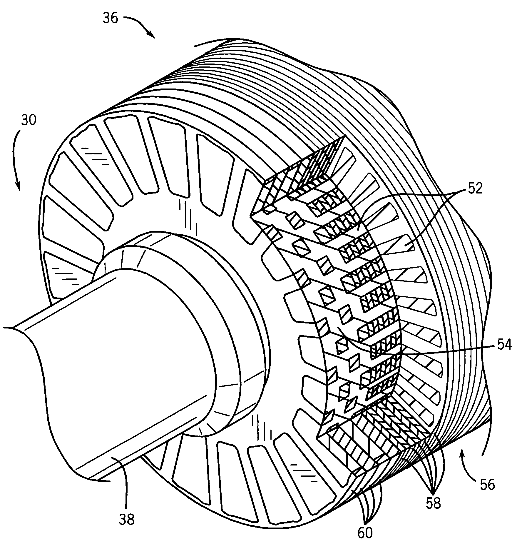
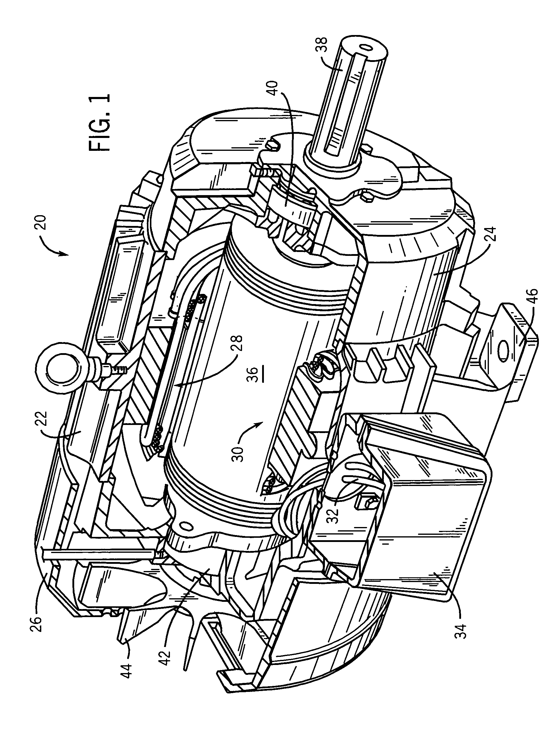
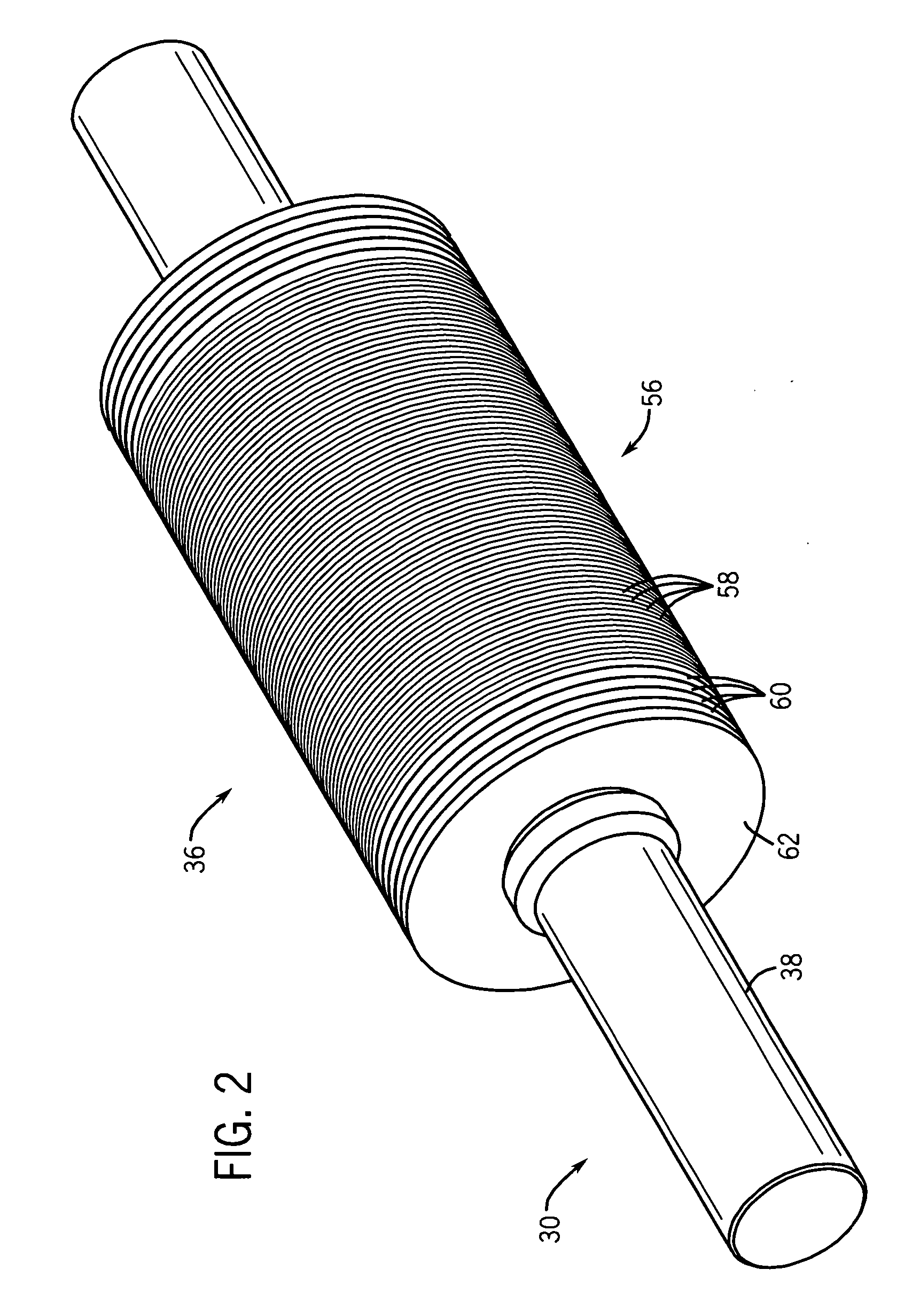
[0020] Turning now to the drawings, and referring first to FIG. 1, an electric motor is shown and designated generally by the reference numeral 20. In the embodiment illustrated in FIG. 1, motor 20 is an induction motor housed in an enclosure. Accordingly, motor 20 includes a frame 22 open at front and rear ends and capped by a front end cap 24 and a rear end cap 26. The frame 22, front end cap 24, and rear end cap 26 form a protective shell, or housing, for a stator assembly 28 and a rotor assembly 30. Stator windings are electrically interconnected to form groups, and the groups are, in turn, interconnected. The windings are further coupled to terminal leads 32. The terminal leads 32 are used to electrically connect the stator windings to an external power cable (not shown) coupled to a source of electrical power. Energizing the stator windings produces a magnetic field that induces rotation of the rotor assembly 30. The electrical connection between the terminal leads and the pow...


PUM


Abstract

A rotor configured to receive a cast internal conductive structure is disclosed. The rotor includes a rotor core having a plurality of rotor slots extending through the rotor core. The rotor also includes a plurality of slotted end members adjacent one another and axially aligned with the rotor core. One end member is radially positioned such that the slots of the end member are offset with respect to another end member. A rotating machine having such a rotor and a method of manufacture are also disclosed.

Description

BACKGROUND [0001] The present invention relates generally to the field of electrical rotating machines, such as motors, generators, or the like. More particularly, the present techniques concern the rotor assemblies of such rotating machines. [0002] Electrical rotating machines, such as electric motors, generators, and other similar devices, are quite common and may be found in diverse industrial, commercial, and consumer settings. These machines are produced in a variety of mechanical and electrical configurations. The configuration of these devices may depend upon the intended application, the operating environment, the available power source, or other similar factors. In general, these devices include a rotor surrounded at least partially by a stator. [0003] For instance, one common design of electrical rotating machine is the induction motor, which is used in numerous and diverse applications. In industry, such motors are employed to drive various kinds of machinery, such as pum...

Claims


Application Information

Patent Timeline
IPC IPC(8): H02K17/16
CPCB22D19/0054H02K15/0012H02K17/165
Inventor WHIDDON, RICHARD M.
Owner RELIANCE ELECTRIC TECH
Why Eureka
Try Eureka