Rotor assembly for fishing reels

a technology for fishing reels and rotors, which is applied in fishing reels, applications, fishing, etc., can solve the problems of heavy steel rotors, severe rubbing and abraded steel rotor surfaces and their formed edges, and high cost of steel rotors, so as to improve the performance of steel rotors

Active Publication Date: 2006-08-17
YOUNG JOHN N
View PDF14 Cites 2 Cited by
  • Summary
  • Abstract
  • Description
  • Claims
  • Application Information

AI Technical Summary

Benefits of technology

[0032] From the earliest development of spincasting reels, various parts and mechanisms have been attached to the rotor to improve its performance, but in all cases the rotor has retained its primary release and ...

Problems solved by technology

Steel rotor surfaces and their formed edges are severely rubbed and abraded by fishing line as it is cast or retrieved from spincasting reels.
Steel rotors are heavy.
Steel rotors are costly.
Sheet-forming st...

Method used


Image

  • Rotor assembly for fishing reels
  • Rotor assembly for fishing reels
  • Rotor assembly for fishing reels

Examples


Embodiment Construction

[0051] Certain categories of fishing reels have as a common feature a substantially cup shaped rotor which covers a portion of and is radially aligned with the reel's spool. With related mechanisms, the rotor functions to either release fishing line for casting from the spool of the reel or for retrieving line back onto the spool after casting. It is the purpose of the invention to teach an improved construction of the reel parts as they are used in a conventional manner. The function of the parts may therefore be summarized briefly as follows:

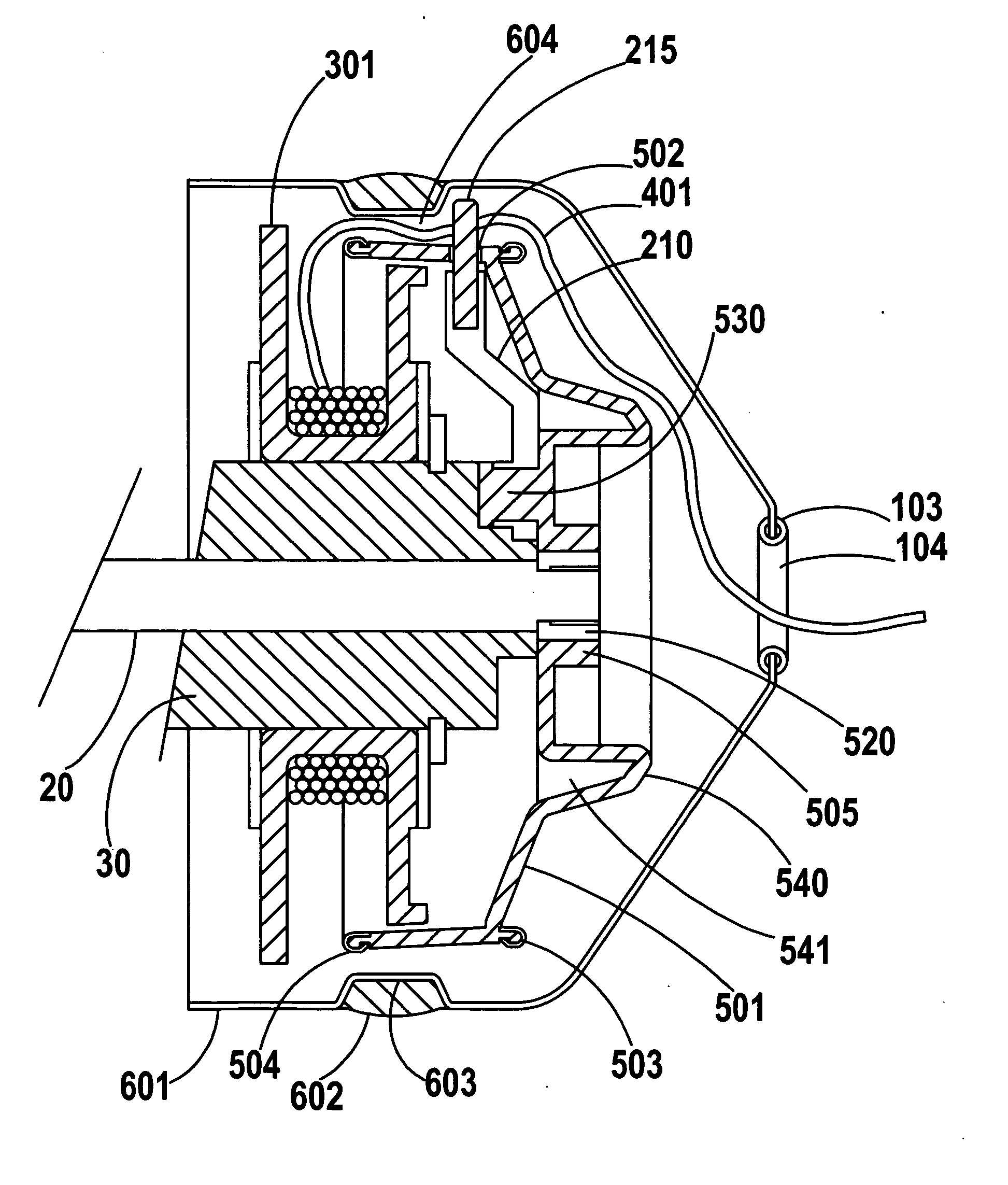
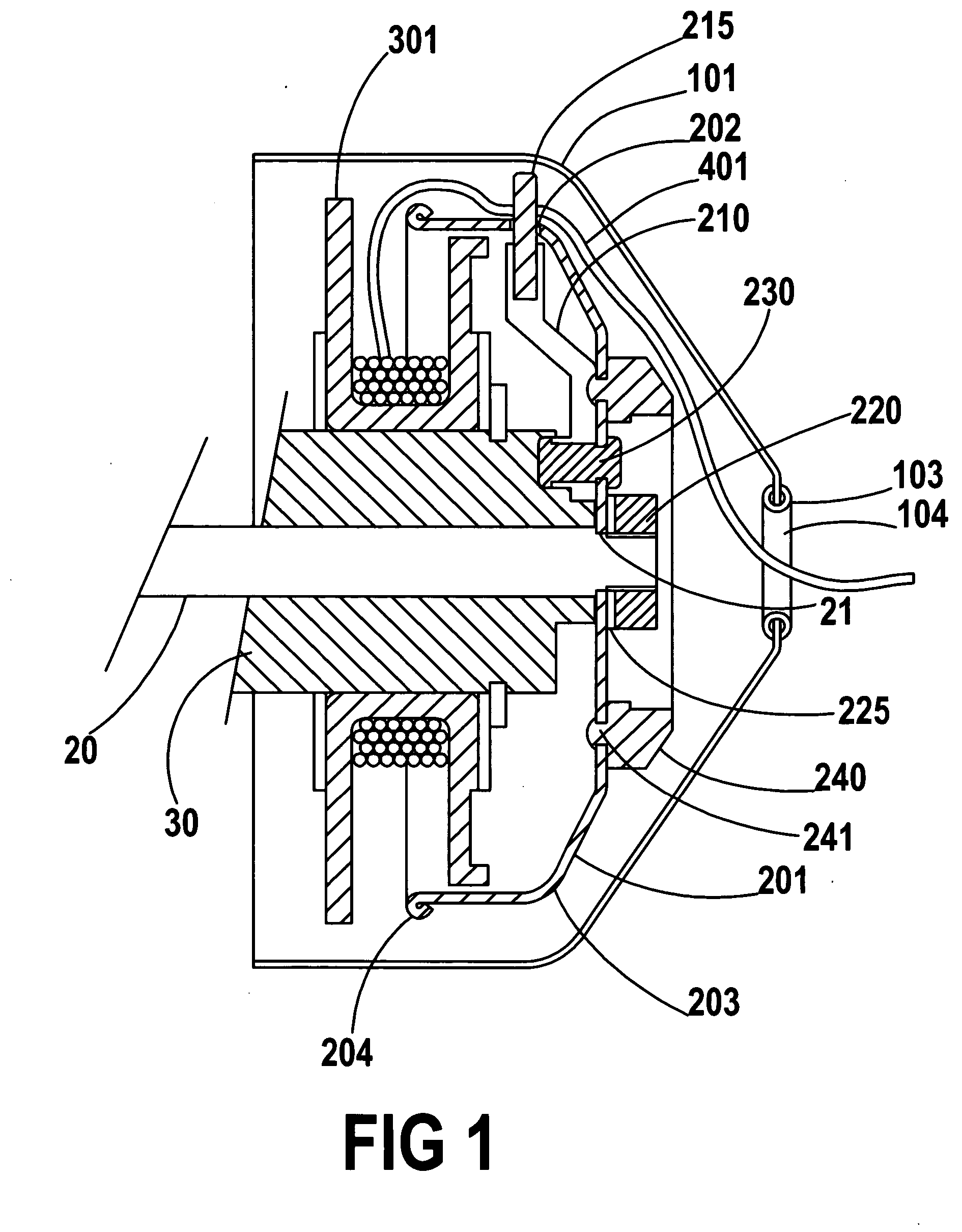
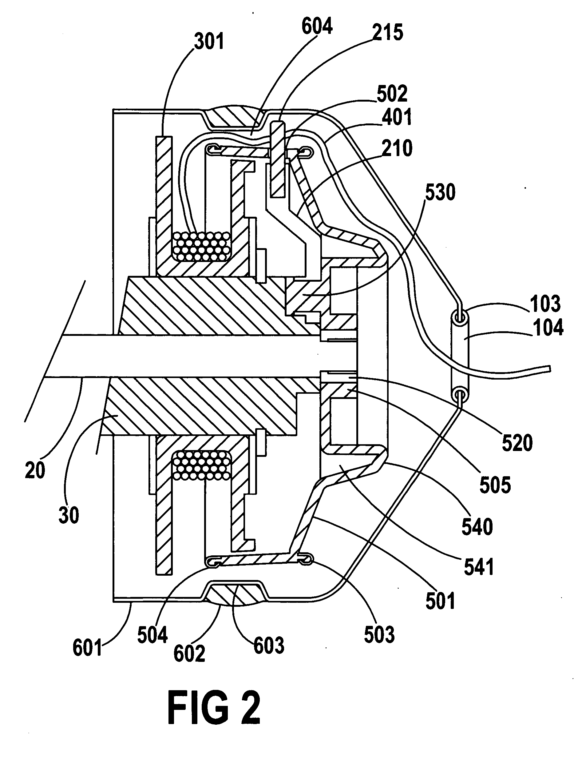
[0052]FIG. 1 shows existing reel art in which Steel Rotor 201 is keyed to Main Shaft 20 at 21 and is held fixed thereto by rotor nut 220 through lock washer 225 so that the Steel Rotor and Main Shaft move in unison. Fixed to the Steel Rotor is Carrier Pivot Support 230 and rotatably fixed on 230 is Pin Carrier 210. Pickup pin 215 is fixed to Pin Carrier 210. Rotor Snubber 240 is attached to the Steel Rotor by Snubber Posts 241.

[0053] Main Sh...


PUM


Abstract

In a reel with a spool a hood and an axially aligned and substantially cup-shaped rotor partially encircling the spool, a molded monocoque frame rotor design in which the monocoque frame is molded to include various features of the rotor and in which the leading and trailing edges of the rotor are of a material substantially different from the monocoque frame.

Description

CROSS-REFERENCE TO RELATED APPLICATIONS [0001] The following references are considered relative prior art. [0002] U.S. Pat. No. 2,299,156 [0003] U.S. Pat. No. 3,044,730 [0004] U.S. Pat. No. 3,381,914 [0005] U.S. Pat. No. 3,858,822 [0006] U.S. Pat. No. 3,900,167 [0007] U.S. Pat. No. 4,359,196 [0008] U.S. Pat. No. 4,376,518 [0009] U.S. Pat. No. 4,637,569 [0010] U.S. Pat. No. 4,640,470 [0011] U.S. Pat. No. 4,756,487 [0012] U.S. Pat. No. 4,778,120 [0013] U.S. Pat. No. 4,778,123 [0014] U.S. Pat. No. 4,768,731 [0015] U.S. Pat. No. 4,997,143 [0016] U.S. Pat. No. 5,167,381 [0017] U.S. Pat. No. 5,213,279 [0018] U.S. Pat. No. 5,244,165 [0019] U.S. Pat. No. 5,393,004 [0020] U.S. Pat. No. 5,427,325 [0021] U.S. Pat. No. 5,467,932 [0022] U.S. Pat. No. 5,740,976 [0023] U.S. Pat. No. 6,299,086 [0024] U.S. Pat. No. 6,375,107 [0025] U.S. Pat. No. 6,612,064 [0026] U.S. Pat. No. 6,581,318STATEMENT REGARDING FEDERALLY SPONSORED RESEARCH OR DEVELOPMENT [0027] Not applicable REFERENCE TO SEQUENCE LISTING,...

Claims


Application Information

Patent Timeline
IPC IPC(8): A01K89/01
CPCA01K89/0102
Inventor YOUNG, JOHN N.
Owner YOUNG JOHN N
Why Eureka
Try Eureka