
Surface mount type temperature-compensated crystal oscillator

a temperature-compensated crystal and oscillator technology, applied in the direction of oscillator stabilization, electrical equipment, oscillator generators, etc., can solve the problems of inability to make definite measurement of oscillation characteristics, difficult to discover the cause of oscillation defects, and inability to measure oscillation characteristics. , to achieve the effect of preventing the influence of the oscillating frequency, preventing stray capacitance, and facilitating the design

Inactive Publication Date: 2007-04-05
NIHON DEMPA KOGYO CO LTD
View PDF2 Cites 27 Cited by
  • Summary
  • Abstract
  • Description
  • Claims
  • Application Information

AI Technical Summary

Benefits of technology

[0020] An object of the present invention is to provide a surface mount type temperature-compensated crystal oscillator which is small in variation from a designed oscillating frequency value and can be designed easily.
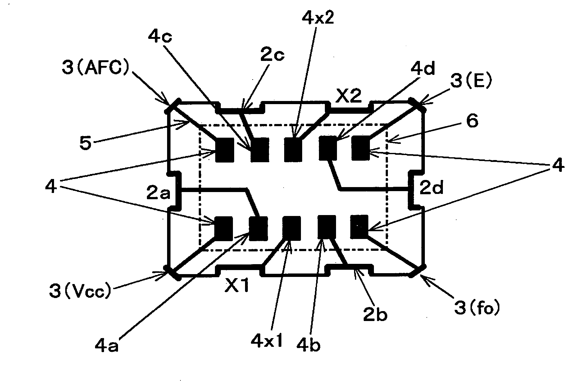
[0022] In a surface mount type temperature-compensated crystal oscillator according to the present invention, since a side surface of a container body is provided with a crystal inspection terminal together with a data writing terminal, oscillation characteristics of a crystal unit alone can be measured so that analysis on oscillating defects becomes feasible therefore even after a product is shipped. Since the crystal inspection terminal is provided on the side surface along the long side among side surfaces of the container body, a crystal IC terminal of an IC chip and the crystal inspection terminal can be connected with a short conductive path. Accordingly, line capacitance, stray capacitance and the like can be made small, preventing influence onto oscillating frequency and facilitating the design. In that case, although the conductive path from the IC chip to the data writing terminal becomes long, the conductive path is outside the oscillation closed loop of the oscillation circuit and is irrelevant to oscillating operations and, therefore, even if that conductive path might be long, the oscillating frequency is not adversely affected.

Problems solved by technology

Consequently, after completion as a product, oscillation characteristics for crystal unit alone will not be measurable.
In that case, even if failure might occur such as oscillation defects and the like in a temperature-compensated crystal oscillator after a product is shipped, for example, oscillation characteristics for the crystal unit alone cannot be analyzed and therefore it is difficult to discover the cause for the oscillation defects.
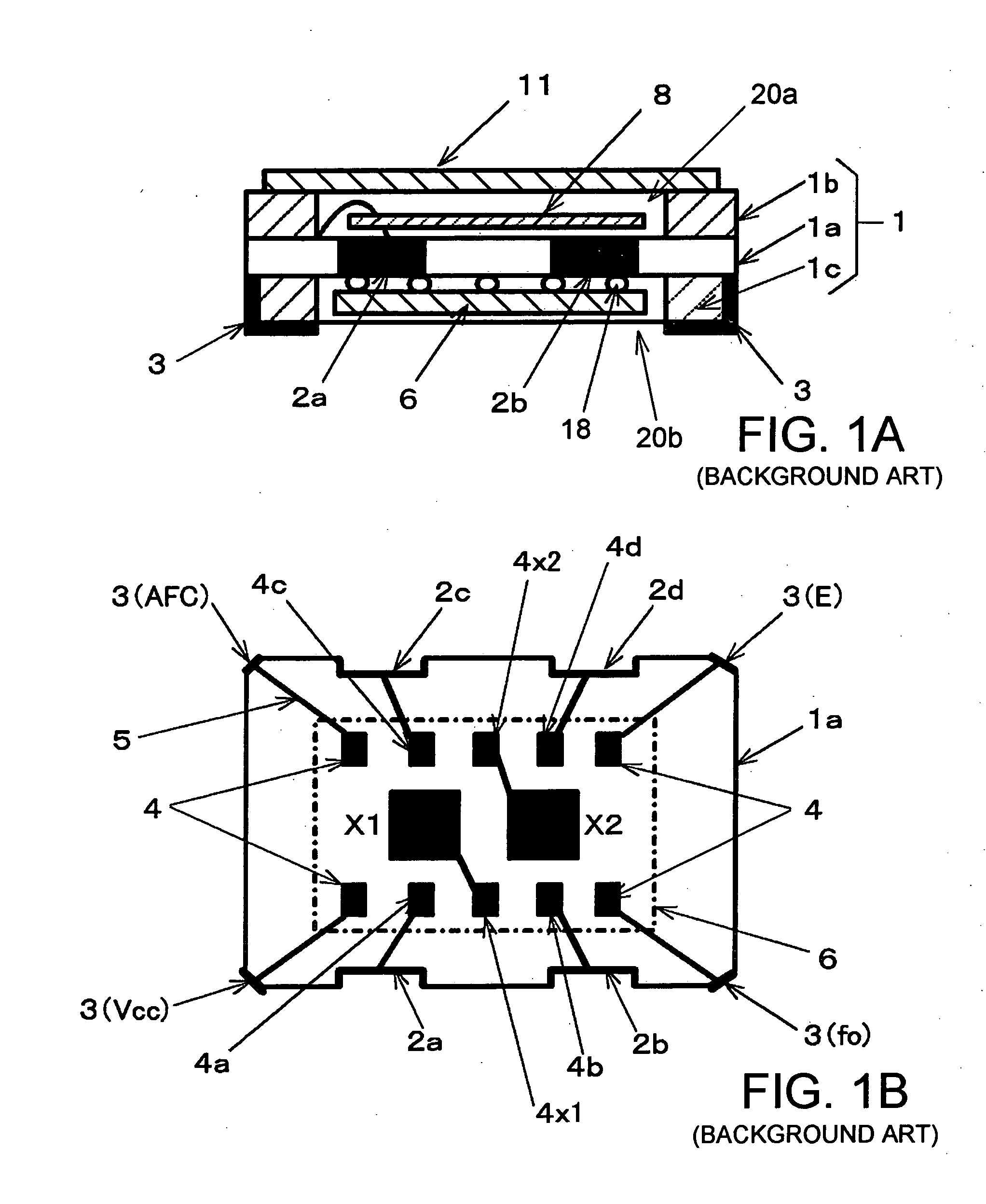
Due to a probe of a measuring device for measuring oscillation characteristics, crystal inspection terminals X1, X2 require such a size as not less than 0.6×0.6 mm, for example; however, if temperature-compensated crystal oscillators are further downsized, the crystal inspection terminal will be smaller than this size so that it will be impossible to make definite measurement on oscillation characteristics.
In consideration of ongoing downsizing of crystal oscillators, the side surface area of container body 1 will be small and, therefore, it is difficult to provide a total of three terminals, or crystal inspection terminals and data writing terminals, on one exterior surface.
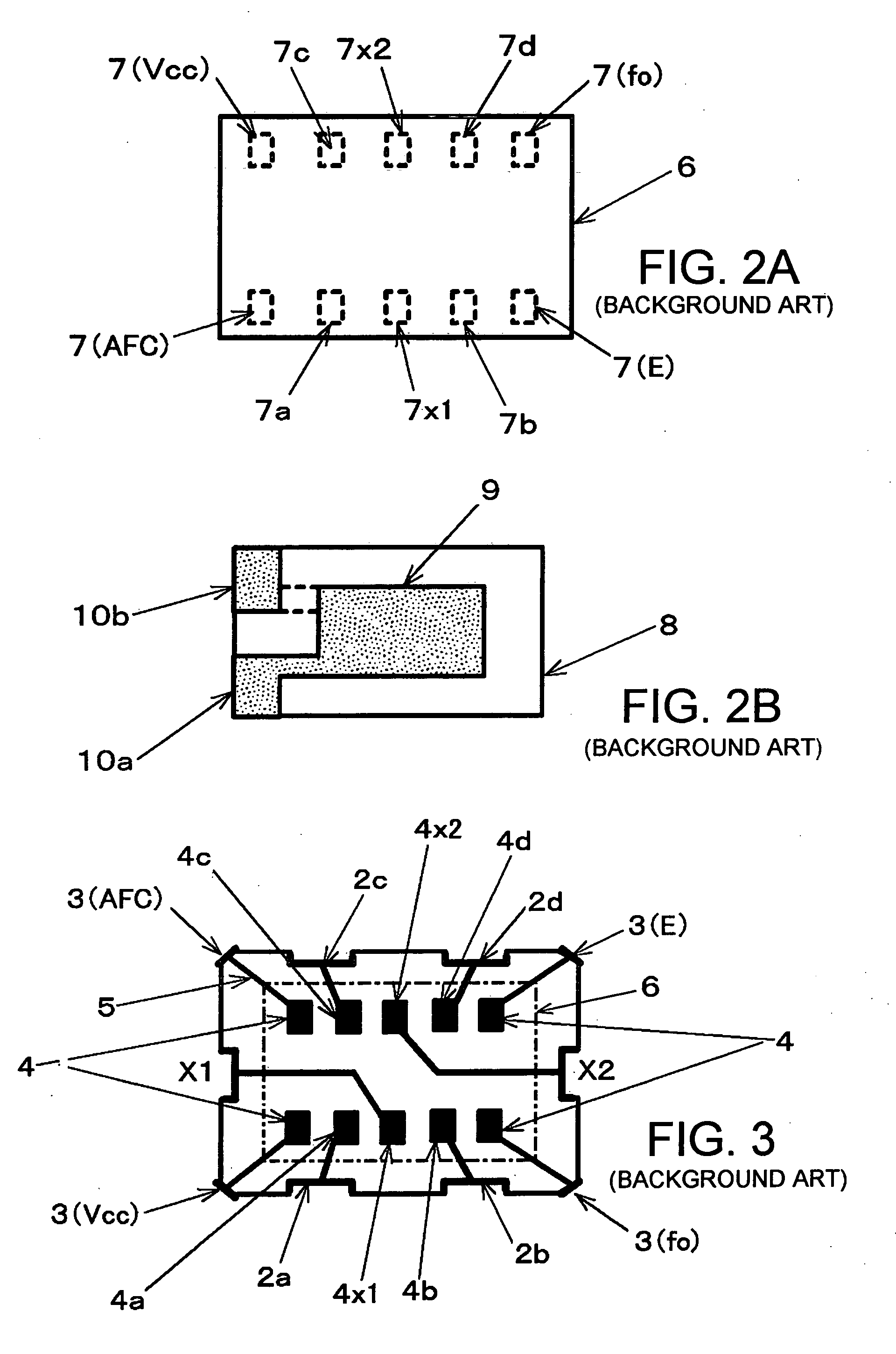
However, when crystal inspection terminals are arranged in this way, and considering the arrangement of IC terminal 7 in IC chip 6 described above, conductive path 5 connecting each of crystal inspection terminals X1, X2 provided on the both end faces in the direction of a long side from crystal circuit terminals 4×1, 4×2 will be long on center layer 1a. This means that line capacitance, stray capacitance and the like in the conductive path directly connected to crystal chip 8 increases, and consequently gives rise to such a problem of complicated design of crystal oscillators or complicated quality management because, for example, oscillating frequency may largely deviate from the designed value.

Method used


Image

  • Surface mount type temperature-compensated crystal oscillator
  • Surface mount type temperature-compensated crystal oscillator
  • Surface mount type temperature-compensated crystal oscillator

Examples


Embodiment Construction

[0030] A surface mount type temperature-compensated crystal oscillator according to an embodiment of the present invention is constructed and shaped similar to the one described with FIG. 3 described above; however it is different, in arrangement of a crystal inspection terminal and a data writing terminal, from the one shown in FIG. 3. That is, the crystal oscillator of the present embodiment comprises, as shown in FIG. 1A, container body 1 having a first recess and a second recess, crystal blank 8 hermetically sealed in first recess 1, and IC chip 6 fixed onto a bottom surface of the second recess by flip chip bonding. Container body 1 has a flat, substantially rectangular parallelepiped outside shape having short sides and long sides when mounted on a wiring substrate and viewed from above. In container body 1, four corners of a main face having the second recess are provided with likewise mounting electrodes as described above. IC chip 6 is identical to the one used in the above...


PUM


Abstract

A surface mount type temperature-compensated crystal oscillator includes a crystal blank; an IC chip integrating an oscillation circuit using the crystal blank and a temperature compensation mechanism of compensating frequency temperature characteristics of the crystal blank; and a substantially rectangular parallelepiped container body for surface mounting having a first recess of housing the crystal blank and a second recess of housing the IC chip. Respective side surfaces corresponding to the long sides of the container body are provided with crystal inspection terminals for inspecting oscillation characteristics of the crystal blank and respective side surfaces corresponding to the short sides are provided with data writing terminals for writing temperature compensation data to the temperature compensation mechanism. A conductive path electrically connecting the IC chip to the crystal inspection terminal is formed to be shorter than a conductive path electrically connecting the IC chip to the data writing terminal.

Description

BACKGROUND OF THE INVENTION [0001] 1. Field of the Invention [0002] The present invention relates to a temperature-compensated crystal oscillator in which a crystal unit, an oscillation circuit using the crystal unit and a temperature compensation mechanism for compensating frequency-temperature characteristics of the crystal unit are housed inside a container for surface mounting, and more particularly, to a temperature-compensated crystal oscillator having a data writing terminal for writing temperature compensation data into the temperature compensation mechanism and a crystal inspection terminal for carrying out an operation test of the crystal unit. [0003] 2. Description of the Related Arts [0004] For its small size and lightweight as well as high stability of an oscillating frequency against a temperature change, a temperature-compensated quartz crystal oscillator of a surface mount type is widely used as a reference source for a frequency and time, in particular, in a portabl...

Claims


Application Information

Patent Timeline
IPC IPC(8): H03B5/32
CPCH03B5/04H03B5/36H03H9/0552H03H9/1021
Inventor MIZUMURA, HIROAKIMORIYA, KOUICHI
Owner NIHON DEMPA KOGYO CO LTD
Learn More