Electromagnetic-force-balancing-type electronic balance

a technology of electronic balance and force balancing, applied in the field of magnetic circuits, to achieve the effect of counteracting an imbalance in hysteresis characteristic, enhancing adjustability, and high process yield

Inactive Publication Date: 2007-04-05
SHIMADZU CORP
View PDF7 Cites 4 Cited by
  • Summary
  • Abstract
  • Description
  • Claims
  • Application Information

AI Technical Summary

Benefits of technology

[0029] The fifth aspect of the invention has the aforementioned function. For example, the yoke may be formed to have a height allowing the second permanent magnet to reliably protrude from the yoke, and the connection member may be formed to have a height coming into contract with an outer peripheral surface. Thus, in addition to the effects obtained by the invention as in the fourth aspect of the invention, the fifth aspect of the invention can achieve an effect of being able to provide an electromagnetic-force-balancing-type electronic balance having enhanced adjustability and high process yield.
[0030] The sixth aspec

Problems solved by technology

The remaining air gap creates a magnetic resistance in th

Method used


Image

  • Electromagnetic-force-balancing-type electronic balance
  • Electromagnetic-force-balancing-type electronic balance
  • Electromagnetic-force-balancing-type electronic balance

Examples


first embodiment

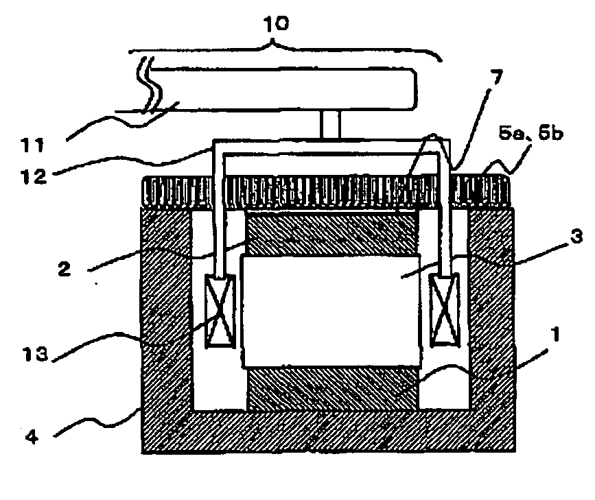
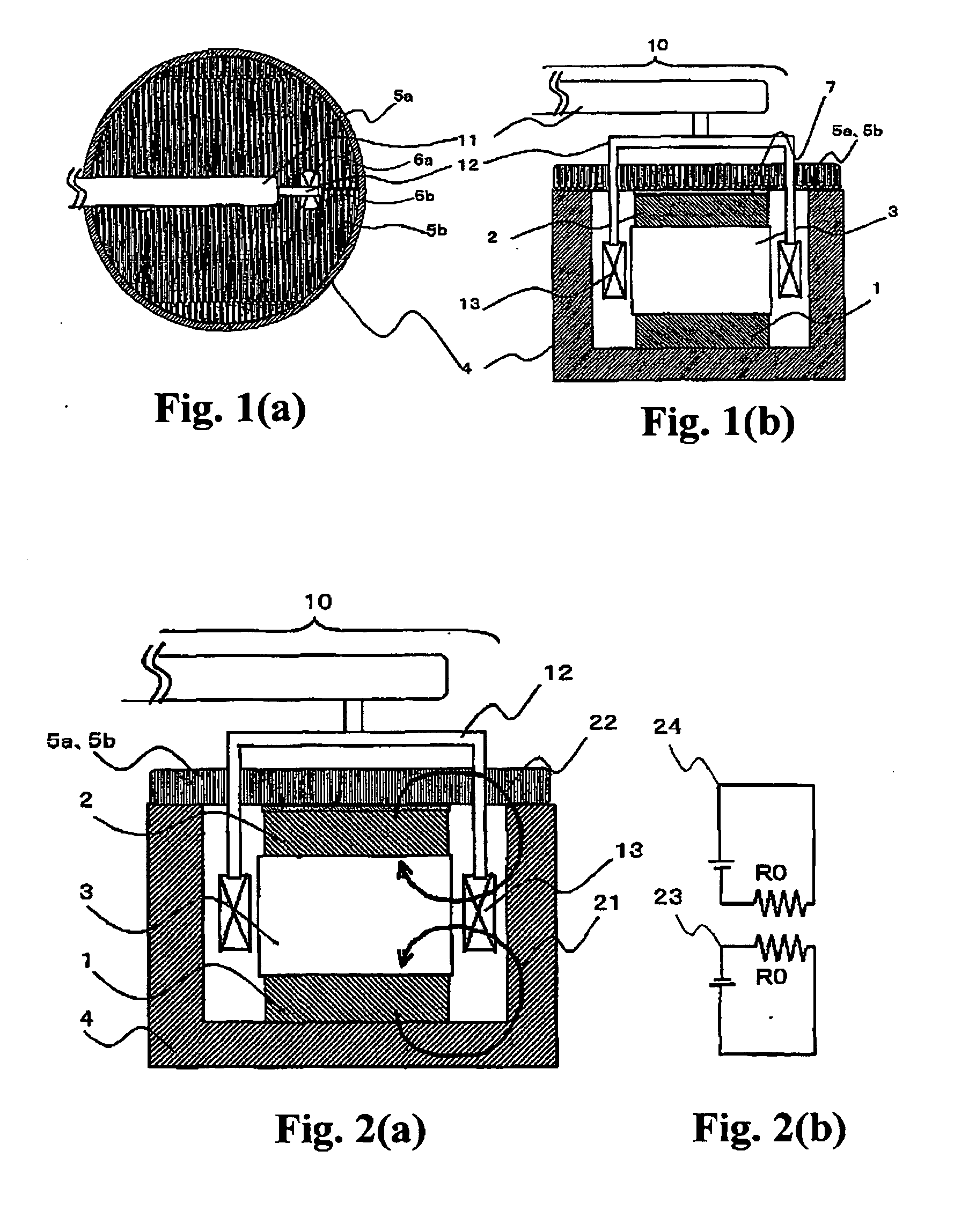
[0042] As shown in FIG. 1, a magnetic circuit for an electromagnetic-force-balancing-type (or electromagnetic-force-compensation-type) electronic balance according to a first embodiment of the present invention comprises first and second permanent magnets 1, 2 disposed such that their north (N) poles are opposed to one another, a pole piece 3 sandwiched between the first and second permanent magnets 1, 2, a tubular-shaped yoke 4 having an opening only on one side thereof and an inner surface in contact with the first permanent magnet 1, a pair of covers 5a, 5b in contact with or adjacent to the second permanent magnet 2, and a connection member 7 disposed between the second permanent magnet 2 and the cover pair 5a, 5b. The electronic balance has a movable assembly 10 which comprises a movable lever 11, a force-coil mounting plate 12 fixed to one end of the movable-section lever 11, and a force coil 13 fixedly mounted to the force-coil mounting plate 12. The electronic balance also h...

second embodiment

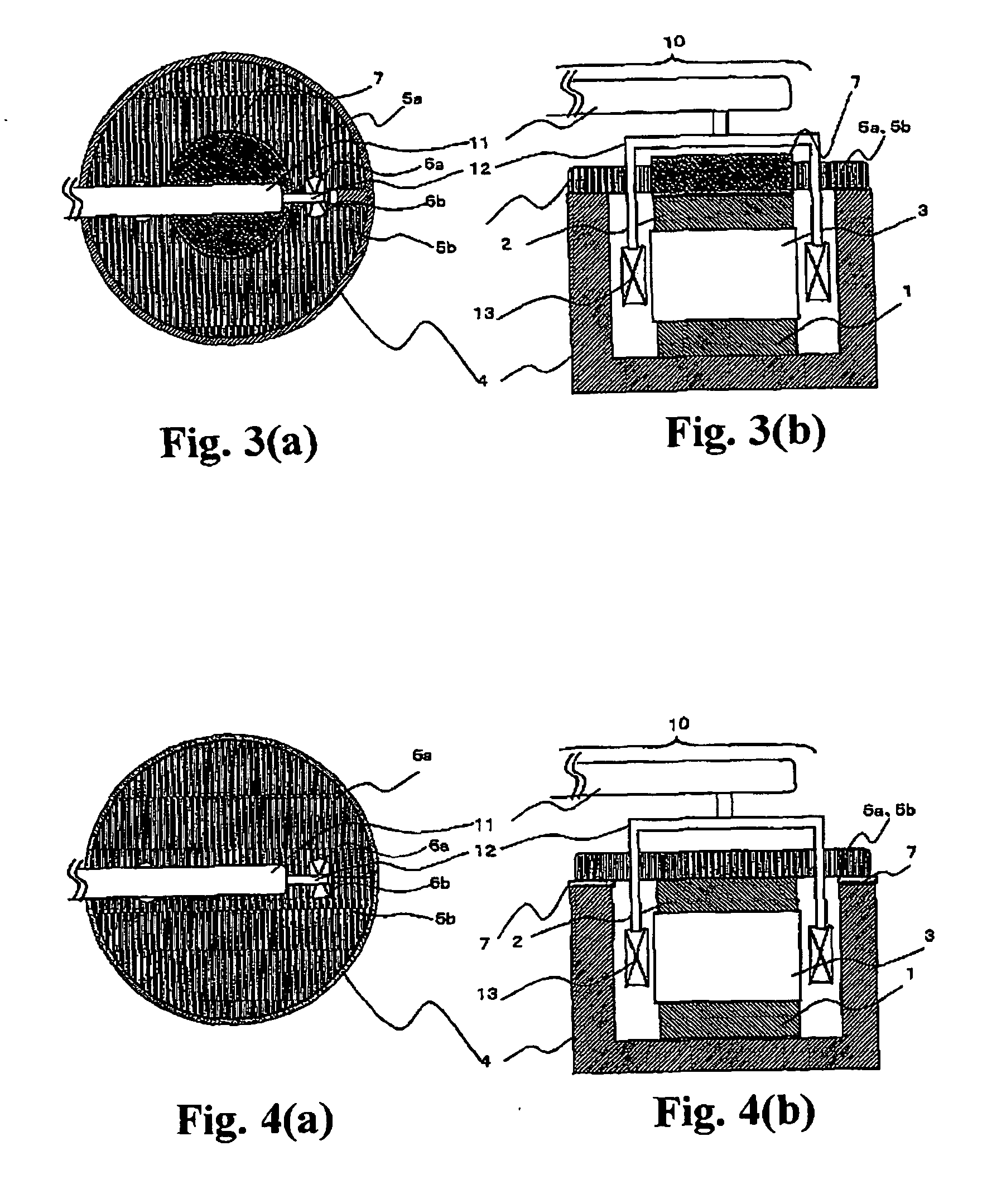
[0051] As shown in FIG. 3, except that the cover pair 5a, 5b is formed with a cutout for the connection member 7, and the connection member 7 is disposed to protrude upward from a top surface of the cover pair 5a, 5b through the cutout, an electromagnetic-force-balancing-type electronic balance according to a second embodiment of the present invention has the same structure as that in the first embodiment. This electronic balance is assembled according to the following process (Assembling steps 1 and 3 are the same as those in the first embodiment, and their descriptions will be omitted.).

[0052] (Assembling Step 2)

[0053] A specific one of the connection members 7 which has a thickness allowing the second permanent magnet 2 to adequately protrude upward from the top surface of the cover pair 5a, 5b is adhesively attached onto the top surface of the second permanent magnet 2. The above assembling steps 1 and 2 may be performed for the magnetic circuit independently.

[0054] (Assembli...

third embodiment

[0056] As shown in FIG. 4, except that the yoke 4 is formed to have a height less than that of the second permanent magnet after assembling, and the connection member 7 is formed in a ring shape and sandwiched between the cover pair 5a, 5b and the yoke 4, an electromagnetic-force-balancing-type electronic balance according to a third embodiment of the present invention has the same structure as that in the first embodiment. This electronic balance is assembled according to the following process (Assembling steps 1, 3 and 4 are the same as those in the first embodiment, and their descriptions will be omitted.).

[0057] (Assembling Step 2)

[0058] Plural number of the connection members 7 different in thickness are prepared in advance. A specific one of the connection members 7 which has a thickness allowing a height of the specific connection member 7 when placed on the upper edge of the yoke 4 to become equal to that of the second permanent magnet 7 is selected, and adhesively attache...


PUM


Abstract

Disclosed is an electromagnetic-force-balancing-type electronic balance having a magnetic circuit which includes a yoke 4, a first permanent magnet 1, a pole piece 3, a second permanent magnet 2 and a cover 5. A connection member 7 made of a magnetic material is disposed in an air-gap region included in the magnetic circuit. The connection member 7 may be disposed between the second permanent magnet 2 and the cover 5 or between the cover 5 and the yoke 4 to facilitate assembling operations. Alternatively, first and second gap-defining members 8, 9 made of a non-magnetic material may be disposed, respectively, between the first permanent magnet 1 and the yoke 4 and between the second permanent magnet 2 and the cover 5, to provide symmetric properties in magnetic sub-circuits so as to counteract an imbalance in hysteresis characteristic. The present invention can suppress adverse influences of a magnetic resistance caused by an air gap existing in the magnetic circuit of the electronic balance.

Description

TECHNICAL FIELD [0001] The present invention relates to a magnetic circuit suitably usable in an electromagnetic-force-balancing-type electronic balance. BACKGROUND ART [0002] As shown in FIG. 9, a magnetic circuit incorporated in a conventional electromagnetic-force-balancing-type (or electromagnetic-force-compensation-type) electronic balance comprises first and second permanent magnets 1, 2 disposed such that their magnetic poles of the same polarity are opposed to one another, a pole piece 3 sandwiched between the first and second permanent magnets 1, 2, a tubular-shaped yoke 4 having an opening only on one side thereof and an inner surface in contact with the first permanent magnet 1, and a pair of covers 5a, 5b in contact with or adjacent to the second permanent magnet 2 (see, for example, the following Patent Publication 1). The electromagnetic-force-balancing-type electronic balance has a movable assembly 10 which comprises a movable lever 11, a force-coil mounting plate 12 ...

Claims


Application Information

Patent Timeline
IPC IPC(8): H01F7/08
CPCY10S177/05G01G7/02
Inventor IIDUKA, ATUSHISHIMAUCHI, KUNIOYOSHIKUWA, NOBUYUKI
Owner SHIMADZU CORP
Why Eureka
Try Eureka