

[signal adjuster]
Patent Information
- Authority / Receiving Office
- US · United States
- Current Assignee / Owner
- SURE FIRE ELECTRICAL
- Publication Date
- 2007-04-05
- Estimated Expiration
- Not applicable · inactive patent
Smart Images
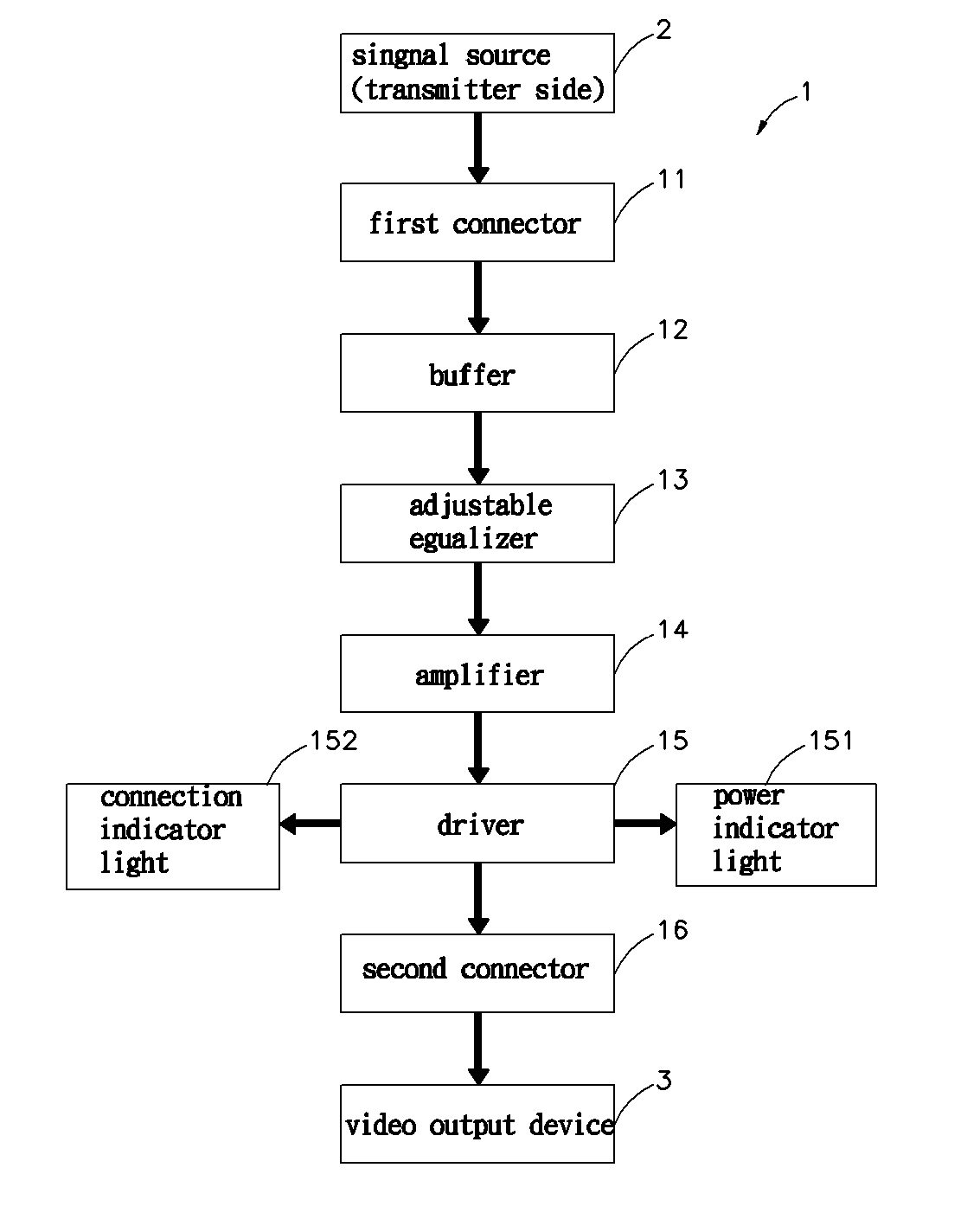
Figure 1 
Figure 2 
Figure 3
Abstract
Description
BACKGROUND OF THE INVENTION
[0001] 1. Field of the Invention
[0002] The present invention relates to signal adjuster and more particularly, to a signal adjuster for connection between a signal source and a video output device through a high-frequency signal cable to enhance the strength of the high frequency signal from the signal source and to amplify the enhanced high frequency signal for output to the video output device.
[0003] 2. Description of the Related Art
[0004] In recent years, there is a great change in audio and video application industry. In consequence, a variety of audio and video devices have been developed and intensively used in our daily life. These audio and video devices including CD / VCD / DVD players, high resolution digital TVs, video phones and videoconference systems commonly use a digitalized technology to process audio signal in video signal. Following different application requirements, related protocols have been well defined. For example, DVI (Digital Vi...