Audio output apparatus

a technology of audio output and output device, which is applied in the direction of electrical transducers, volume compression/expansion, gain control, etc., can solve the problems of poor usability, difficult to select only the sounds that you want to hear, and point to problems for practical use, so as to improve the separation of audibility of a plurality of sounds.

Active Publication Date: 2007-04-05
YAMAHA CORP
View PDF26 Cites 34 Cited by
  • Summary
  • Abstract
  • Description
  • Claims
  • Application Information

AI Technical Summary

Benefits of technology

[0014] The invention has been made to solve the problems. An object is to provide an audio output apparatus which can separate sounds that individual viewers desire to hear from other sounds to listen to the sounds exce

Problems solved by technology

However, when sounds are normally outputted at the same time, it is almost impossible to select only the sounds desired to hear.
However, in the case of the television receiver like this, a viewer who watches the second contents has to use earphones all the time, causing a problem that usability is not good.
However, in the case of the audio output apparatus of Patent Reference 1 using the array speaker like this, it has some points to be problems for practical use.
However, when the absolute sound levels of a plurality of sound signals inputted to the array speaker are greatly varied, the sound pressure difference realized by directivity control over the array speaker is likely to be cancelled.
When the sound pressure difference between the target contents and the other contents becomes insufficient, the sounds of the other contents become annoying

Method used


Image

  • Audio output apparatus
  • Audio output apparatus
  • Audio output apparatus

Examples


first embodiment

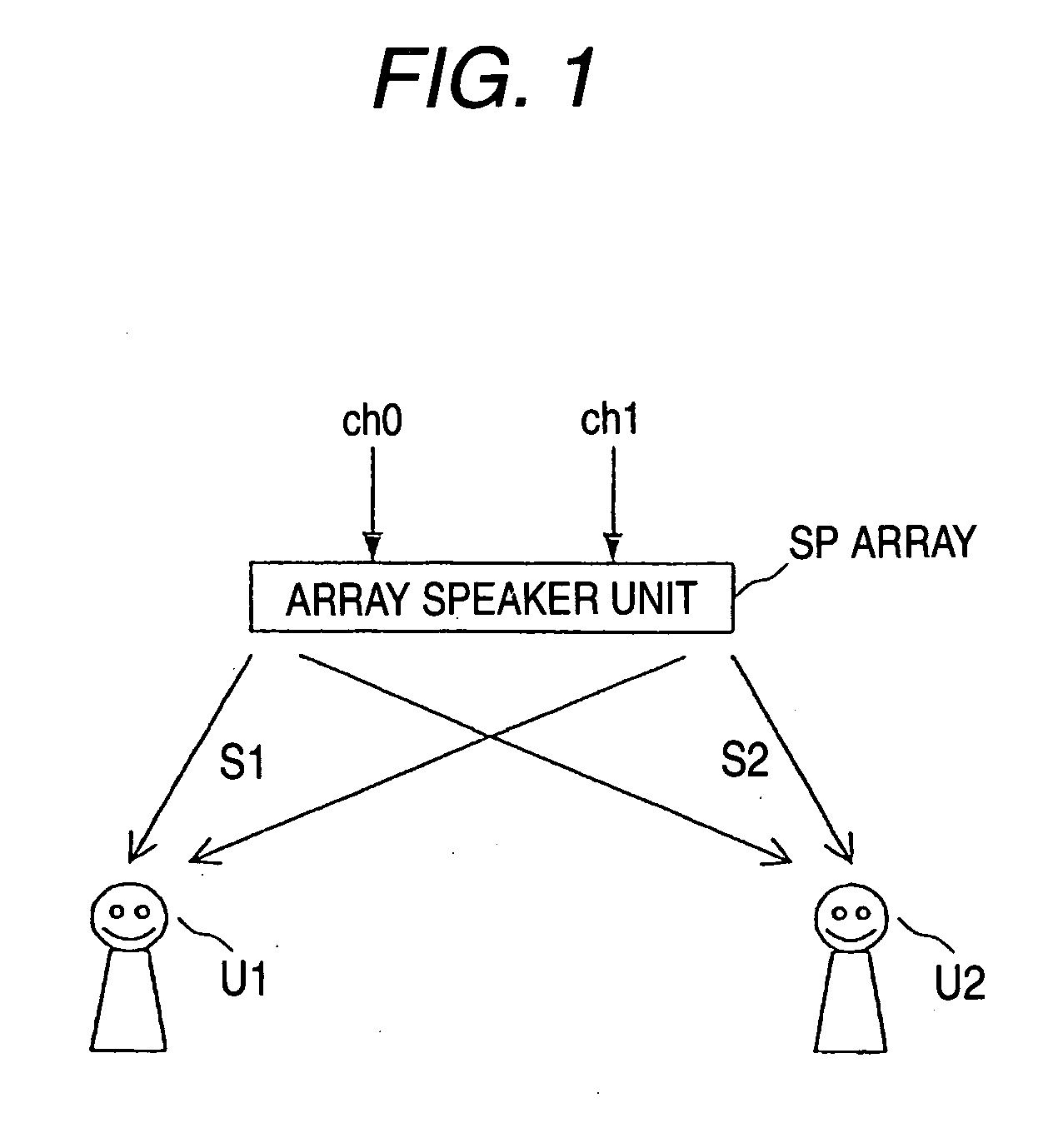
[0069] Hereinafter, embodiments of the invention will be described in detail with reference to the drawings. FIG. 1 is a diagram illustrative of the principle of a first embodiment.

[0070] As similar to the audio output apparatus before, in an audio output apparatus according to the embodiment, directivity is controlled to emit sounds S1 and S2 from an array speaker unit SParray so that the first sound S1 and the second sound S2 separately have different directivities. However, at this time, the sound levels are adjusted so as to equal the levels of a first sound signal ch0 and a second sound signal ch1 which are the base of the sounds S1 and S2, and the sound signals ch0 and ch1 are inputted to the array speaker unit SParray.

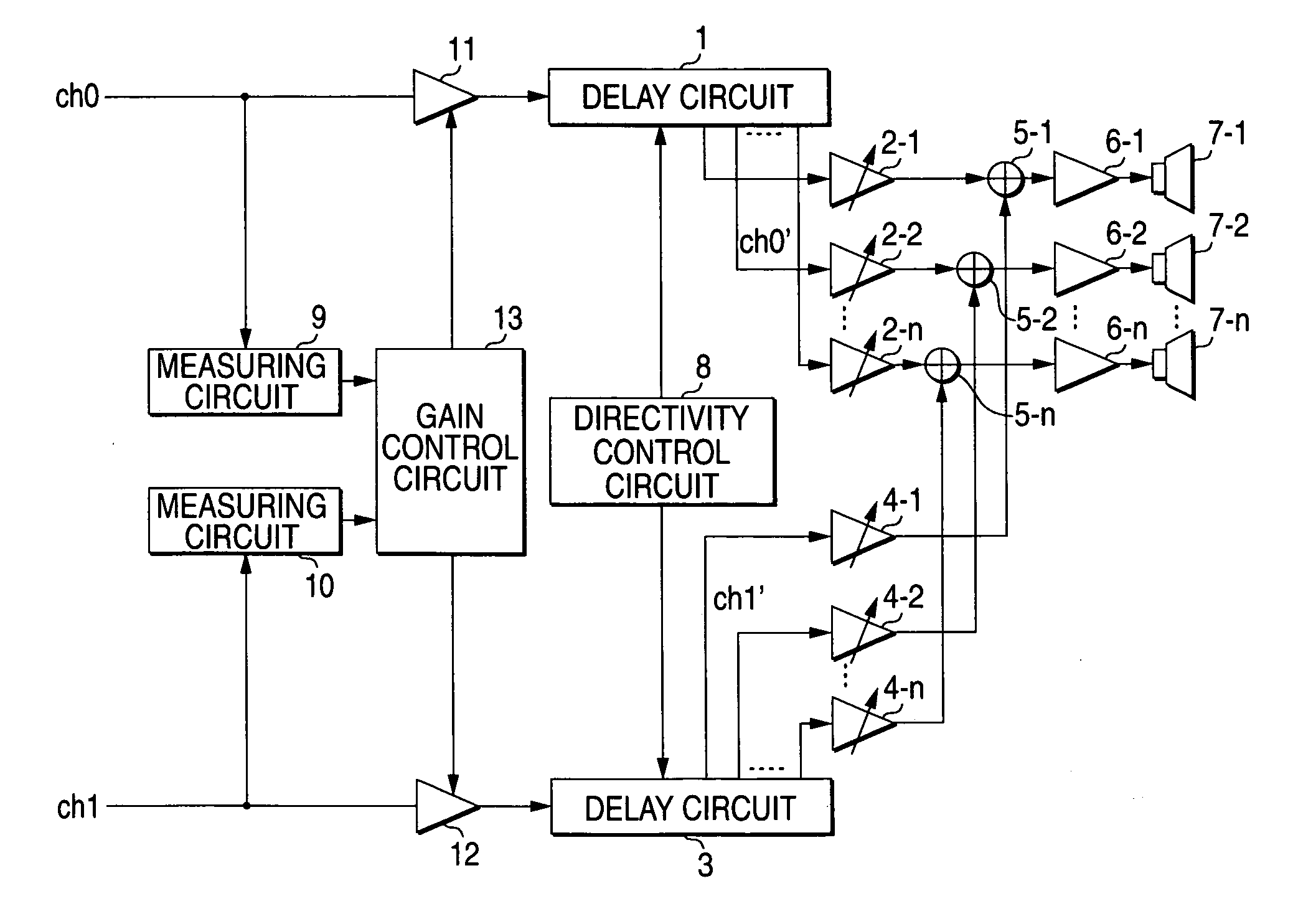
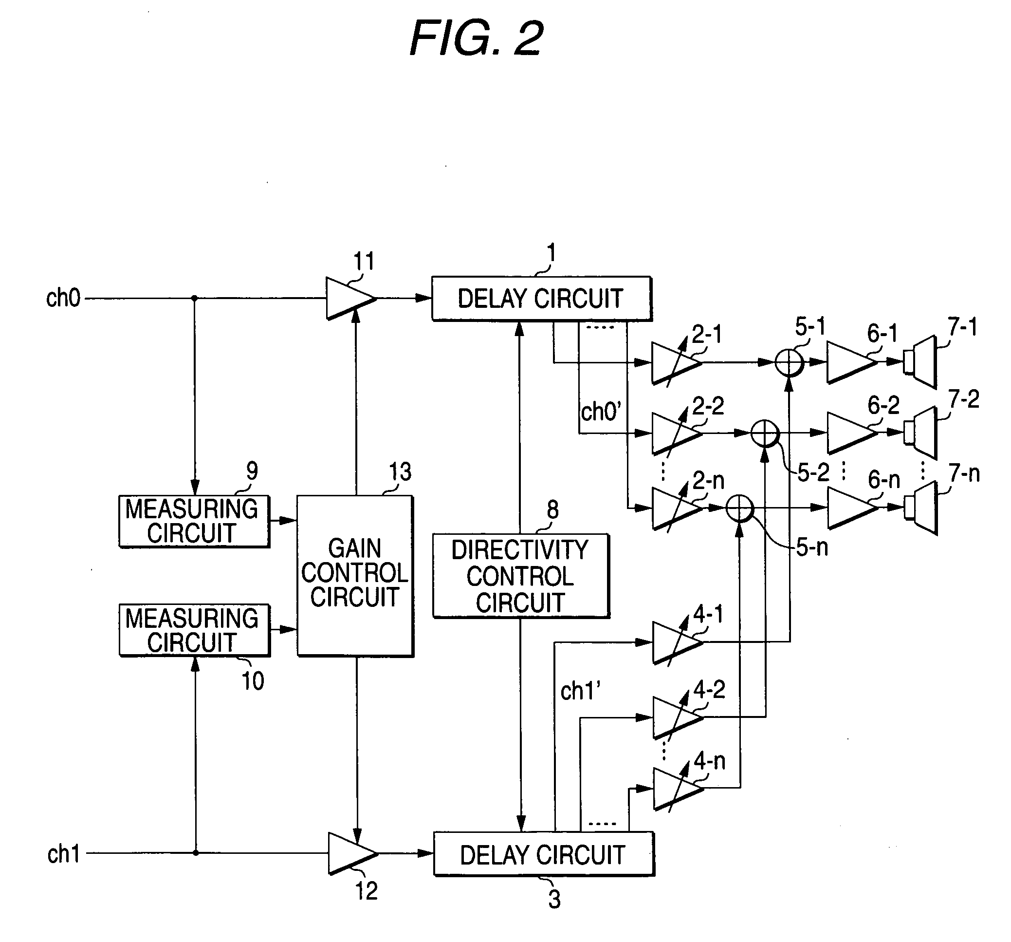
[0071]FIG. 2 is a block diagram showing the configuration of the audio output apparatus according to the first embodiment of the invention. The audio output apparatus shown in FIG. 2 has a measuring circuit 9 which measures the level of the first sound signal ...

second embodiment

[0086] Next, a second embodiment of the invention will be described. FIG. 6 shows a block diagram showing the configuration of an audio output apparatus according to the second embodiment of the invention, and the same numerals and signs are designated to the same configuration as that shown in FIG. 1. The audio output apparatus according to the embodiment shows a more specific example of the first embodiment.

[0087] A measuring circuit 9 according to the embodiment is formed of a rectifier circuit 101 and peak hold circuits 102 and 103. The rectifier circuit 101 rectifies the inputted first sound signal ch0 to the absolute value. The peak hold circuits 102 and 103 hold and output the greatest value among input values up to now in such a way that the hold value is maintained when the value inputted from the rectifier circuit 101 is equal to or smaller than the current hold value whereas an input value is made to a new hold value when the input value exceeds the hold value. When such...

third embodiment

[0096] In the first and second embodiments, the gain coefficients of the sound level adjusting circuits 11 and 12 are set so as to equal the levels of the first sound signal ch0 and the second sound signal ch1 outputted to the array speaker unit (the delay circuits 1 and 3). However, the gain coefficients may be set so that the difference between the first sound signal ch0 and the level of the second sound signal ch1 is made constant.

[0097]FIG. 7 is a block diagram showing the configuration of an audio output apparatus according to a third embodiment of the invention, and the same numerals and signs are designated to the same configuration as that shown in FIG. 6. In the audio output apparatus according to the embodiment, a gain control circuit 13a is used instead of the gain control circuit 13 shown in FIG. 6. The gain control circuit 13a is added with a function that adds a given amount of offset set by a viewer to the outputs of the subtracters 107, 110, 113 and 116 in the gain ...


PUM


Abstract

An audio output apparatus has a measuring circuit which measures the levels of at least two sound signals, a sound level adjusting module (a sound level adjusting circuit and a gain control circuit) which adjusts a sound level so as to equal the levels of the sound signals based on the levels measured at the measuring circuit, and an array speaker unit (a delay circuit, a multiplier, an adder, an amplifier and a speaker unit) which emits sounds in accordance with the sound signals outputted from the sound level adjusting module in different directivities respectively.

Description

TECHNICAL FIELD [0001] The present invention relates to an audio output apparatus which emits a plurality of sounds at the same time in different directivities respectively. BACKGROUND OF THE INVENTION [0002] As typified by a drop in the price of the plasma television, the screen of television receivers for ordinary households is becoming greater. For the diversity of television receivers using a large screen such as a wide screen in particular, there are many plasma television receivers which have a function that the screen is split into two parts to watch different programs (contents) at the same time. At this time, it is easy to watch the desired contents of pictures shown on the screen in multiple windows. However, when sounds are normally outputted at the same time, it is almost impossible to select only the sounds desired to hear. On this account, in the television receiver having the function to split the screen into two parts, sounds of first contents are outputted from spea...

Claims


Application Information

Patent Timeline
IPC IPC(8): H03G3/00H03G9/00H03G3/20H03G3/30H03G5/02H03G7/00H04R1/40H04R3/12H04S3/00
CPCH04R1/403H04R3/12H04R2205/022H04R2430/20H04S3/00
Inventor KONAGAI, YUSUKETAKUMAI, SUSUMU
Owner YAMAHA CORP
Why Eureka
Try Eureka