Internal combustion engine

a combustion engine and internal combustion technology, applied in the direction of reciprocating piston engines, positive displacement engines, engine components, etc., can solve the problems of device drawbacks and still leaves rocking couples

Inactive Publication Date: 2007-04-12
RAFFAELE PETER ROBERT +1
View PDF1 Cites 12 Cited by
  • Summary
  • Abstract
  • Description
  • Claims
  • Application Information

AI Technical Summary

Benefits of technology

[0172] In one embodiment, the member includes means to cause the member to move in one direction only. For example, the member may be designed to move in a direction away from the crank, or away from the pressure in the chamber. Once the member has moved in that direction, it may designed to lock at that point, unless the lock is overcome by a force causing the member to move further in the same direction as before. It will be appreciated that this design can enable the invention to be useful in recording maximum pressure or maximum inertia.

Problems solved by technology

However such devices have certain drawbacks.
Whilst this can be partially compensated for in a multi-pair device, this still leaves rocking couples.

Method used


Image

  • Internal combustion engine
  • Internal combustion engine
  • Internal combustion engine

Examples


Embodiment Construction

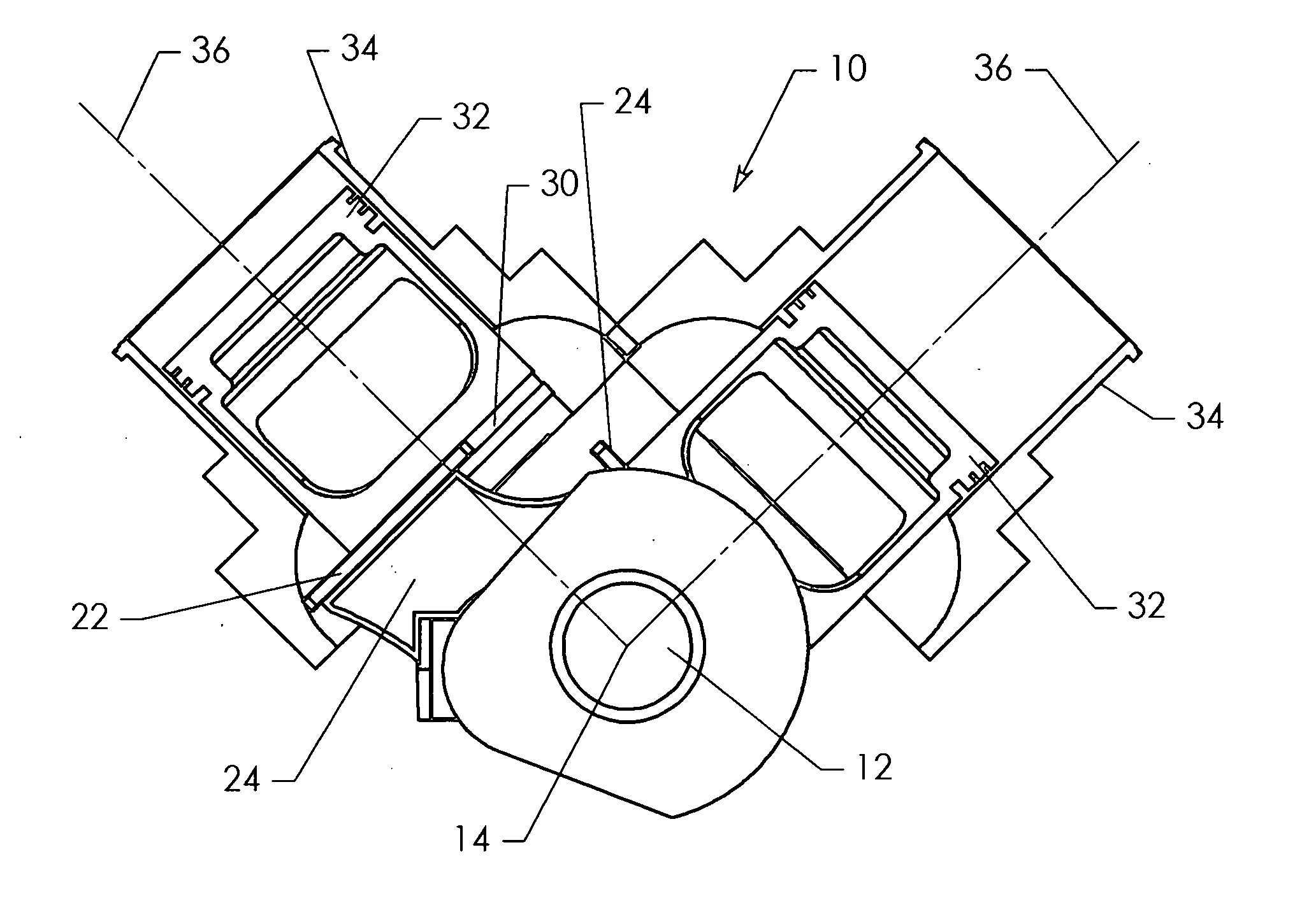
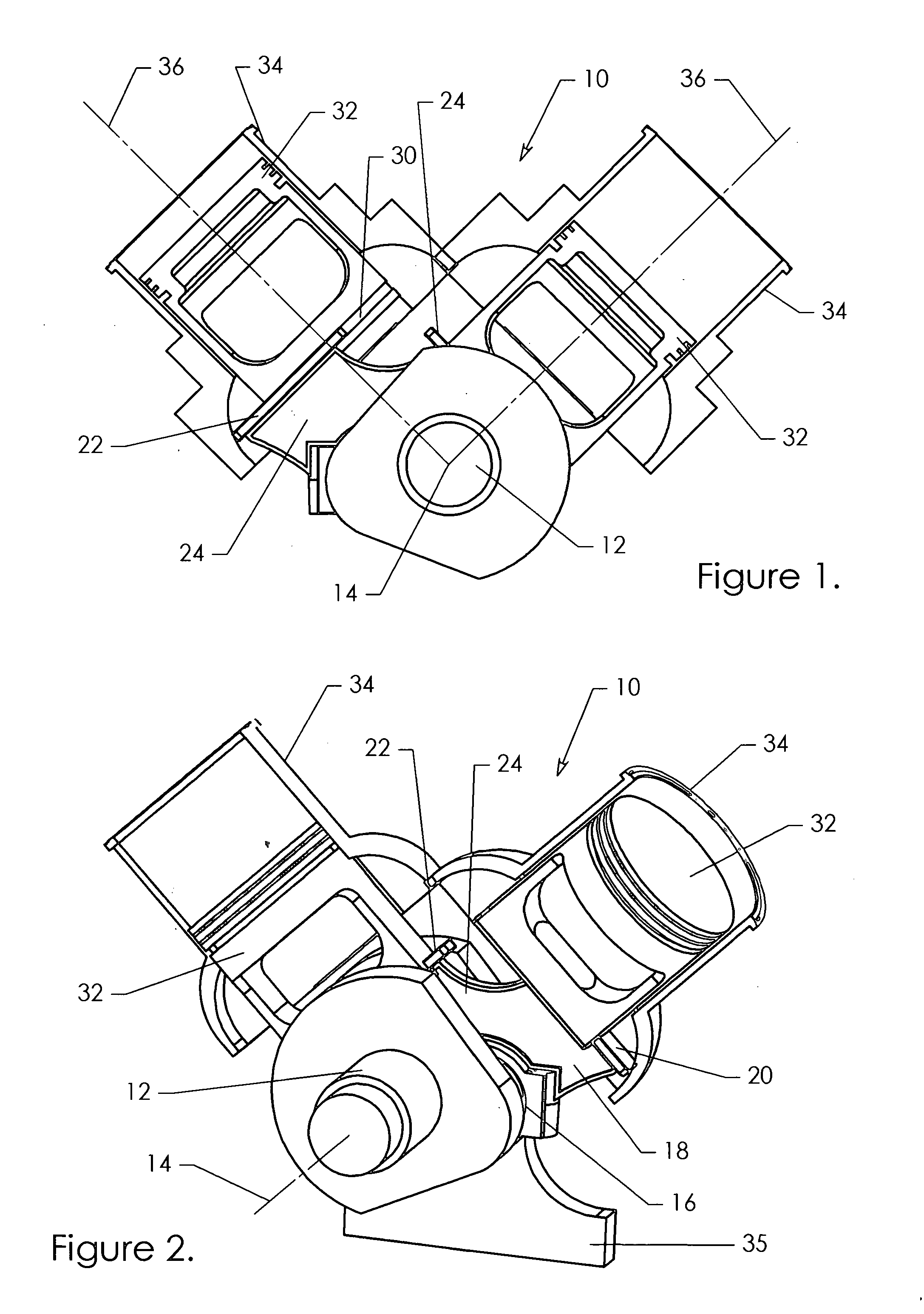
[0271] Referring to FIGS. 1 and 2 there is shown a two piston fluid device 10 which includes a crank 12 mounted for rotation about a crank axis 14. The crank 12 has an offset big end 16, radially distant from the axis 14. Thus as the crank 12 rotates about axis 14, big end 16 will describe a circular orbit around axis 14.

[0272] Rotatably mounted on big end 16 is a connecting means, being a slider 18. The slider has two tongues 20, 22.

[0273] The slider 18 extends generally perpendicular to the axis 14. As best seen in FIG. 2, the sliding surfaces extend axially on either side of the main portion 24 of the slider 18 and so form a T-shaped construction.

[0274] Each of the tongues 20, 22 engages in a T-shaped slot 30 of a respective piston 32. Each piston is mounted in a cylinder 34 for linear movement along a respective cylinder axis 36. Each slot 30 preferably extends substantially perpendicular to the cylinder axis 36 and extends diametrically across the centre of the piston. Both ...


PUM


Abstract

The invention has many aspects. One aspect is that of an internal combustion engine (8010) that has a piston (8020) within a cylinder (8022) and has a crankcase (8012), defining a combustion chamber (8024) and crank volume (8026). A passageway (8032 and 8034) links the combustion chamber (8024) and the crank volume (8026). There is provided valve means (8038) for selectively closing the linking passageway and valve means (8030) for selectively closing and inlet to the crank volume (8026). In another aspect, there is an improvement to a scotch yoke fluid device. A displaceable member for relieving pressure in a variable volume chamber in the cylinder where combustion is occurring is provided. The invention includes a method of varying power output of a scotch yoke device, by choosing cylinder angle, pin angle and firing order in various ways. The invention also deals with other aspects of scotch yoke designs.

Description

[0001] This application claims priority of the filing date of U.S. Ser. No. 10 / 381,953, presently pending, which is a US national phase application under 35 U.S.C. §371 of PCT / AU01 / 01214, filed Sep. 28, 2001, the complete disclosures of which are both hereby expressly incorporated herein by reference.BACKGROUND OF THE INVENTION [0002] 1. The Technical Field [0003] This invention relates to different aspects of reciprocating fluid devices, including those colloquially called “scotch yoke” devices. [0004] 2. The Prior Art [0005] Known scotch yoke devices include one or more pairs of horizontally opposed pistons reciprocating in respective cylinders. Each piston of a pair is rigidly attached to the other so the pair of pistons move as a single unit. The pistons reciprocate along parallel axes which may be coaxial or which may be offset. A crank is provided centrally of the pair of pistons with an offset mounted in a slider. The slider in turn is mounted in the piston assembly between o...

Claims


Application Information

Patent Timeline
Patent Type & Authority Applications(United States)
IPC IPC(8): F02F3/00F01B9/02F02B33/04F02B33/26F02B33/30F02B33/44F02B75/22
CPCF01B9/023F02B33/04F02B33/26F02B33/30F02B33/44F02B75/222F02B2275/32Y02T10/142Y02T10/12F02B75/32
Inventor RAFFAELE, PETER ROBERTRAFFAELE, MICHAEL JOHN
Owner RAFFAELE PETER ROBERT
Why Eureka
Try Eureka