Apparatus for hand control, pressure amplification, and stabilization of medical and industrial devices

a technology for industrial devices and hand control, applied in the direction of application, ultrasonic/sonic/infrasonic diagnostics, curtain suspension devices, etc., can solve the problems of patient skin slipping, moving, and sometimes squirming, and medical practitioners face further physical challenges

Active Publication Date: 2007-04-12
BROWN GARRETT W MR
View PDF22 Cites 75 Cited by
  • Summary
  • Abstract
  • Description
  • Claims
  • Application Information

AI Technical Summary

Benefits of technology

[0025] The angle of the short side is variably fixed in angular reference to the adjacent, roughly vertical, short leg of the parallelogram (with reference to a plumb line that passes through the apex of the triangle), such that the degree of iso-elasticity can remain nominally acceptable, even if the selected spring rate of the resilient member does not conform to the K=P / d formula for iso-elasticity. The length of the short side (and its disposition either above or below the long articulating side) can be continuously adjusted, thus providing for force exertion that varies infinitely between opposing or augmenting gravity. This provides a unique, adjustable, mechanism capable of ‘pressing-down’ on demand—as much or as little as required.
[0029] The present invention thereby provides means and methods to reduce the physical strain currently experienced by medical practitioners who perform ultrasound examinations and similar medical procedures. The present invention may be used to assist in such medical procedures and / or assist in the performance of tasks found in industrial environments.
[0030] The present invention overcomes the shortfalls in the related art by reducing the physical strain experienced by medical practitioners, using means that maintain the hands-on skill, touch, and emotional support provided by a medical practitioner. Unlike computer-controlled robotic arms, the payload, such as a transducer, of the present invention is directly guided by the hands of the medical practitioner, which preserves the ability to make micro fine adjustments in applied pressure based upon objective and subjective information obtained contemporaneously from the patient.
[0031] The present invention overcomes problems in the related art by reducing the physical strain currently experienced by medical practitioners by means that are not perceived by patients as threatening or impersonal.
[0032] The present invention overcomes problems in the related art by not requiring significant retraining of medical practitioners. The set-up, use, and maintenance of the robotic arms in the related art require a different skill set than the current skills of medical practitioners. The present invention attaches seamlessly to current medical devices and functions intuitively, requiring minimal retraining of medical practitioners.

Problems solved by technology

Such medical devices have their own weight and are often attached to cumbersome wires or tubes.
Medical practitioners face further physical challenge due to the need to firmly press the medical device against the skin of a patient for extended periods of time.
With the use of such jelly, the patient's skin presents a slippery, moving, and sometimes squirming surface.
The medical practitioner is then faced with the physical challenge of pressing and systematically moving the medical device on a three dimensional surface that is slippery, moving, and breathing.
Many medical practitioners experience muscle fatigue and injury as a result of the physical exertion required in performing ultrasound examinations or similar examinations with other medical devices.
Most medical procedures do not lend themselves to the use of typical industrial robots or mechanical arms.
These arms rely to a greater or lesser extent on friction to retain a set angle or position, since existing spring geometries do not necessarily provide appropriate or consistent lift throughout the entire angular excursion of the parallelogram links.

Method used


Image

  • Apparatus for hand control, pressure amplification, and stabilization of medical and industrial devices
  • Apparatus for hand control, pressure amplification, and stabilization of medical and industrial devices
  • Apparatus for hand control, pressure amplification, and stabilization of medical and industrial devices

Examples


Embodiment Construction

[0045]

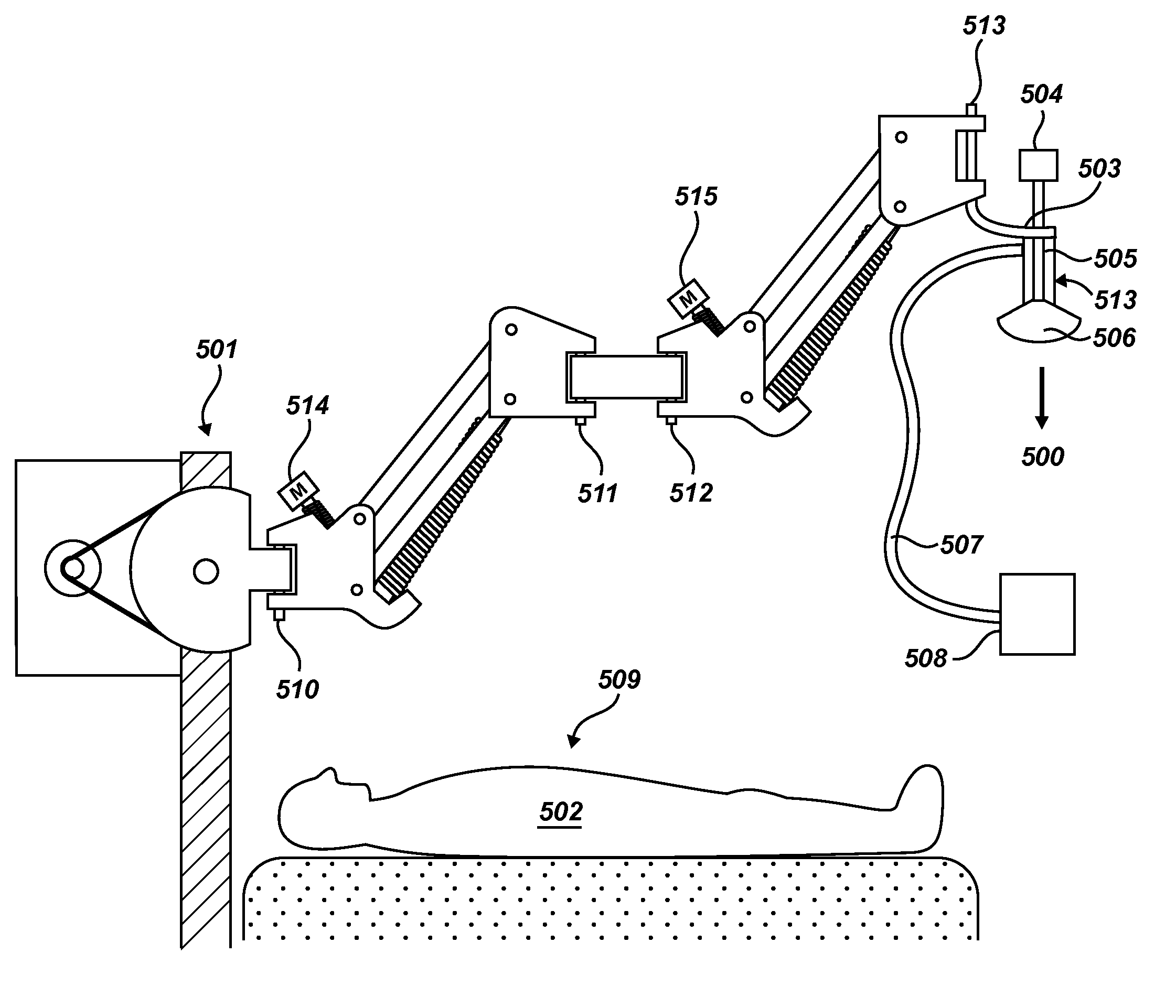
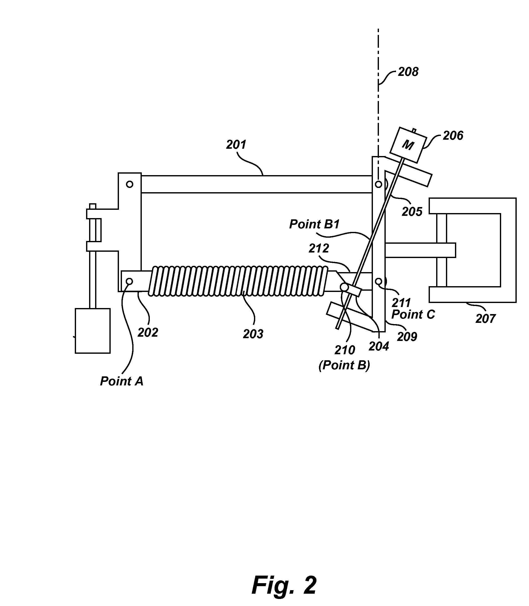
Definition List 1TermDefinitionarticulating, force-An apparatus comprising parallelogramexerting armlinks and resilient means such asdisclosed in U.S. Pat. Nos., 4,208,028 and4,394,075 and 5,360,196 andcontinuation 5,435,515ultrasonographerOne who places a transducer on oragainst the skin of a patient.lateral pressurePressure applied laterally to the side of apatient in vectors displaced as much as90 degrees from that of gravity.down pressurePressure applied toward the floor.medical deviceAny medical instrument such as anultrasound transducer or therapytransducer that is positioned on oragainst a patient.therapy headA housing structure used by the relatedart to contain a medical device.transducerAn ultrasound transducer used for eitherdiagnosis or therapy.

[0046] Currently, a transducer is manipulated upon a patient without mechanical assistance. Many medical devices require firm, but careful pressure to the skin of a patient. An example of such a medical device is a diagnostic...


PUM


Abstract

An equipoising arm structure that can selectively exert force in any direction—lifting, pressing down, or applying lateral bias—with consistent force throughout its range of articulation, comprises a force exerting device having a force exerting structure including a load arm as a first side pivotable about a load pivot, a resilient member attached to the load arm band to a termination point and forming a second side of the force exerting structure. The third side of the structure is formed by a line from the termination point to the load pivot. A first adjustment mechanism moves the termination point to change the length and disposition of the third side of the structure to positions above or below the load pivot. Additional adjustment mechanisms may alter the mounting angle of the entire force exerting structure, and / or the angular relationship between a plurality its force-exerting component devices.

Description

CROSS-REFERENCES TO RELATED APPLICATIONS [0001] The application claims the benefit of U.S. provisional application 60 / 596573 filed on Oct. 4, 2005 which is incorporated herein by reference.STATEMENT REGARDING FEDERALLY SPONSORED RESEARCH OR DEVELOPMENT [0002] Not Applicable. REFERENCE TO A SEQUENCE LISTING [0003] Not Applicable. BACKGROUND OF THE INVENTION [0004] 1. Field of the Invention [0005] The present invention relates to an apparatus for reducing the effort and force required to place and hold a medical instrument on or against a patient. The present invention may be used in performing ultrasound examinations. The present invention includes an equipoising arm structure that can selectively exert force in any direction—lifting, pressing down, or applying lateral bias—with consistent force throughout its range of articulation. [0006] 2. Background of the Present Invention [0007] The placement of a medical device on or against the skin of a patient typically requires physical ex...

Claims


Application Information

Patent Timeline
Patent Type & Authority Applications(United States)
IPC IPC(8): A47H1/10
CPCA61B8/00A61B8/08A61B8/4218A61B19/26A61B2019/263A61B2019/265F16M11/04F16M11/2014F16M11/2092F16M11/24F16M13/02F16M2200/022F16M2200/044F16M2200/063A61B90/50A61B2090/5025A61B2090/506
Inventor STACHOWSKI, ERIC RONALDBROWN, GARRETT W.
Owner BROWN GARRETT W MR
Why Eureka
Try Eureka