Methods of forming sheeting with a composite image that floats and sheeting with a composite image that floats

a technology of composite images and forming methods, applied in the field of forming images on sheeting, can solve the problems of ill-adapted methods for producing three-dimensional images of virtual objects, image must be illuminated,

Active Publication Date: 2007-04-12
3M INNOVATIVE PROPERTIES CO
View PDF98 Cites 88 Cited by
  • Summary
  • Abstract
  • Description
  • Claims
  • Application Information

AI Technical Summary

Benefits of technology

[0019] In yet another embodiment of the above sheeting, the composite image is perceptible across a viewing angle of less than one hundred fifty (150) degrees. In another embodiment of the above sheeting, the composite image appears to move relative to the sheeting as the viewing position changes relative to the sheeting. In another embodiment of the above sheeting, the composite image disappears and reappears when the angle at which the sheeting is viewed changes. In another embodiment of the above sheeting, the color of the composite image changes relative to a viewing angle of less than one hundred fifty (150) degrees. In another embodiment of the above sheeting, the sheeting comprises more than one composite image. In another embodiment of the above sheeting, the composite image is a two-dimensional image. In yet another embodiment of the above sheeting, the composite image is a three-dimensional image.

Problems solved by technology

That is, the perceived depth of the image is inverted so that the object appears “inside out.” This is a major disadvantage, because to correct the image it is necessary to achieve a second optical inversion.
These methods are complex, involving multiple exposures with a single camera, or multiple cameras, or multi-lens cameras, to record a plurality of views of the same object, and require extremely accurate registration of multiple images to provide a single three-dimensional image.
Further, any method that relies on a conventional camera requires the presence of a real object before the camera.
This further renders that method ill-adapted for producing three-dimensional images of a virtual object (meaning an object that exists in effect, but not in fact).
A further disadvantage of integral photography is that the composite image must be illuminated from the viewing side to form a real image that may be viewed.

Method used


Image

  • Methods of forming sheeting with a composite image that floats and sheeting with a composite image that floats
  • Methods of forming sheeting with a composite image that floats and sheeting with a composite image that floats
  • Methods of forming sheeting with a composite image that floats and sheeting with a composite image that floats

Examples


example 1

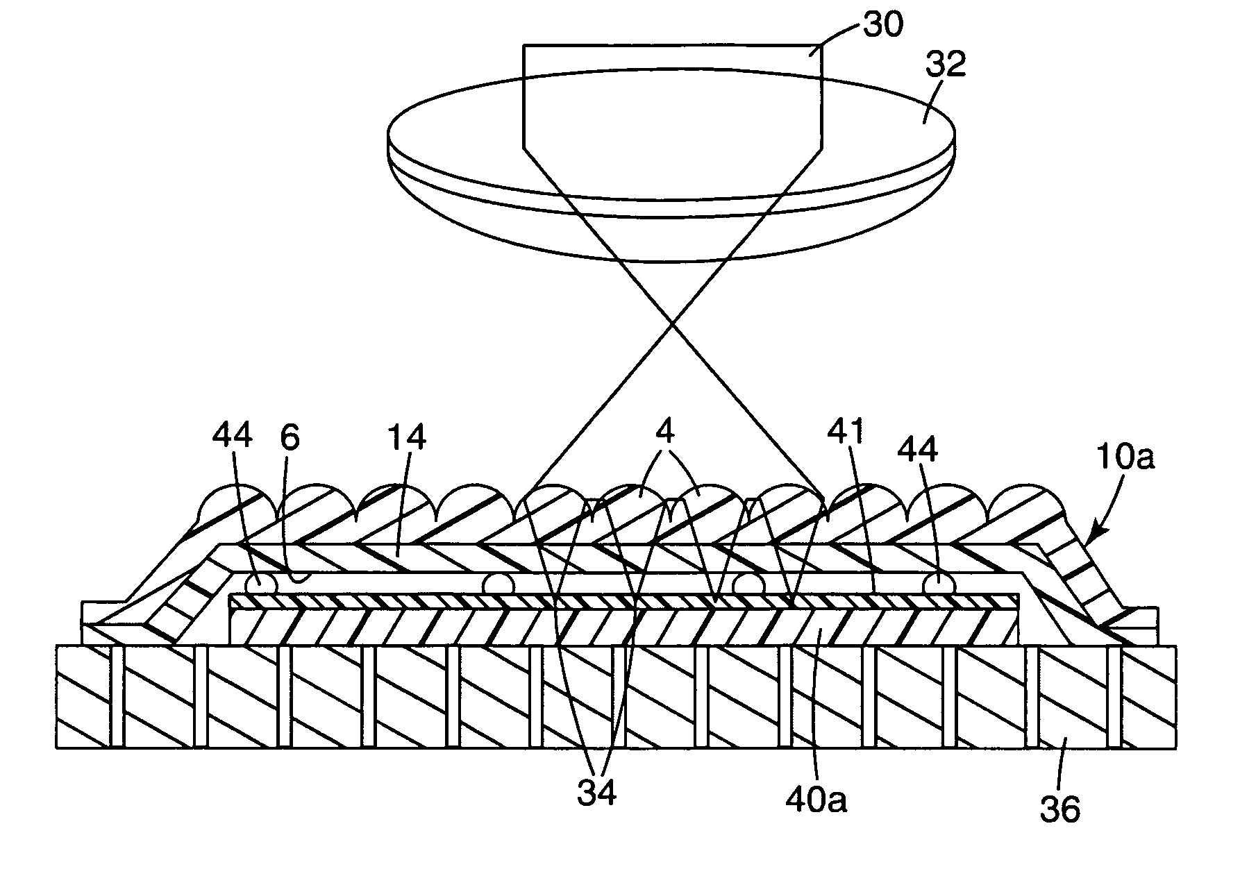
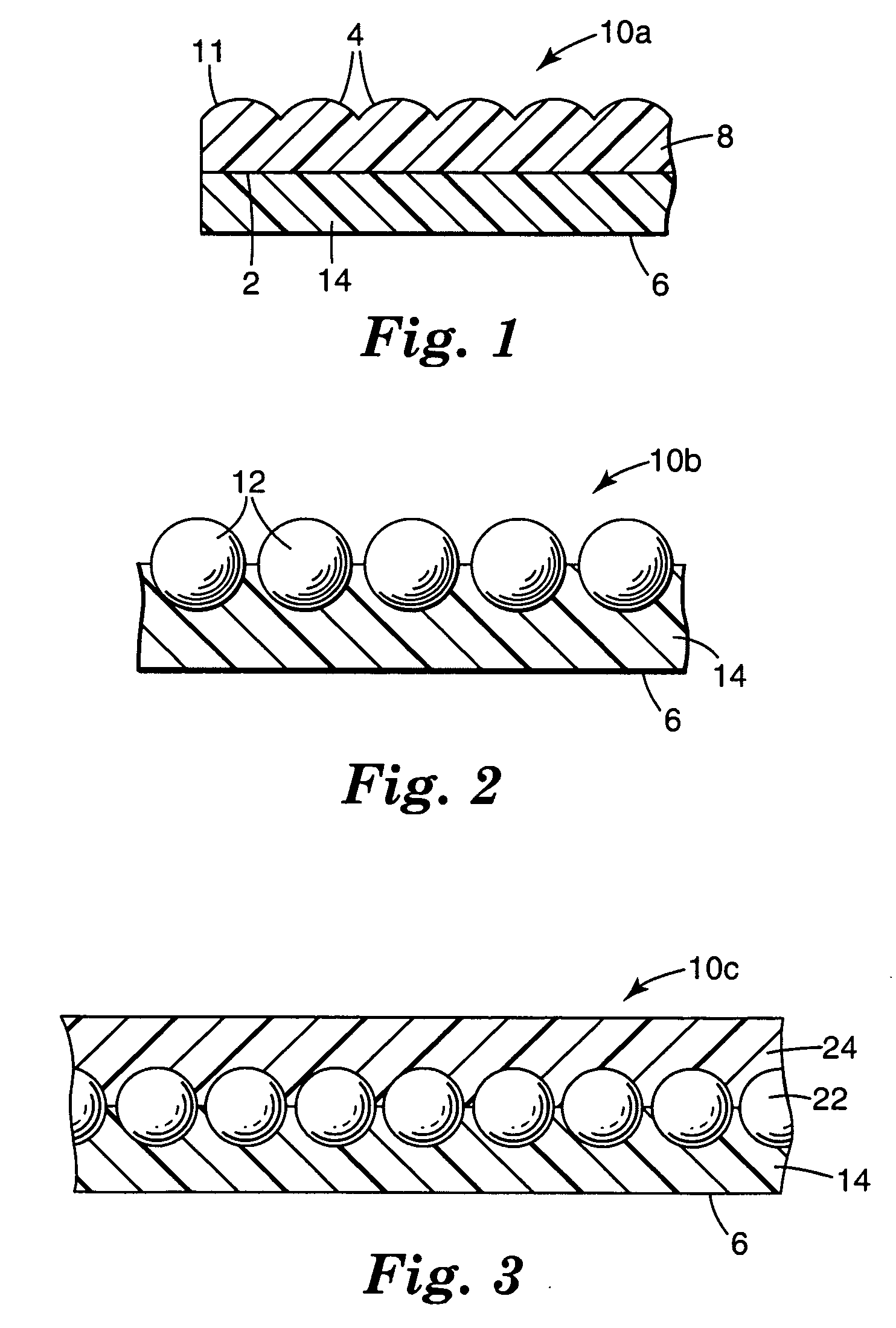
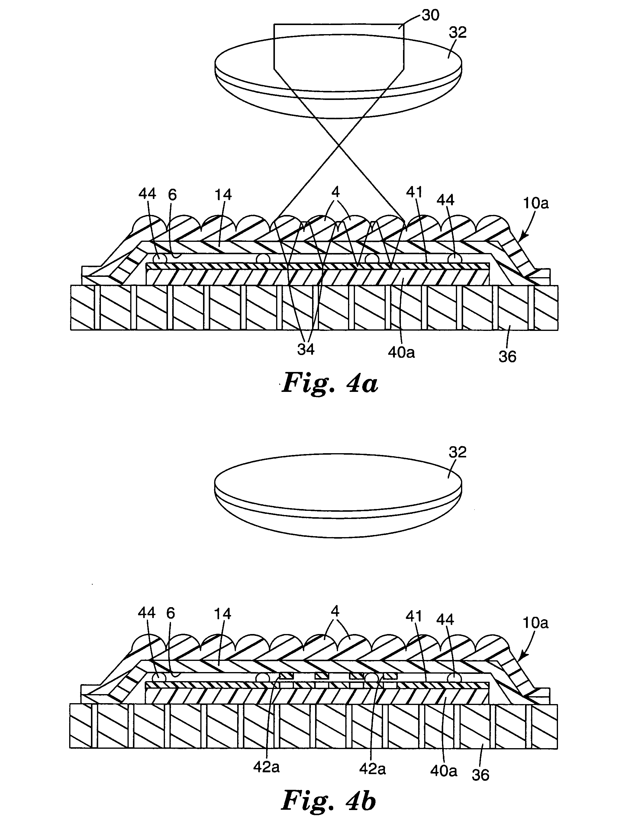
[0099] This example describes a microlensed sheeting with a two-dimensional composite image that appeared to float below the sheeting and a second composite image that was three-dimensional that appeared to float above the sheeting. An optical train of the type depicted in FIG. 16 was used to form the floating images. Imaging, except for the variations described in the optical train below and the mass transfer method described above, was done in accord with the imaging methods taught in U.S. Pat. No. 6,288,842.

[0100] The optical train consisted of a Spectra Physics (Mountain View, Calif.) Hurricane™ Ti-Sapphire Ultrafast Laser operating at its fundamental wavelength of 800 nanometers and at an output power of 45 milliwatts measured at a position of 6.35 millimeters above the microlensed sheeting. The pulse width was approximately 120 femtoseconds and the pulse repetition rate was 250 Hz. A diffuser was not employed in the optical train of this example. A vacuum chuck with a rectang...

example 2

[0104] This example describes a microlensed sheeting with a single color two-dimensional composite image that appeared to float below the sheeting and a second two-dimensional composite image comprised of two colors that appeared to float above the sheeting. An optical train of the type depicted in FIG. 16 was used to form the floating images. Imaging, except for the variations in the optical train described in EXAMPLE 1 and the mass transfer method described above, was done in accord with the imaging methods taught in U.S. Pat.

[0105] No. 6,288,842.

[0106] Donor substrate sections of both cyan and carbon black and microlensed sheeting segments were prepared as set forth in EXAMPLE 1. The donor substrate sections and the microlensed sheeting were arranged on the vacuum chuck as described in EXAMPLE 1.

[0107] An image that would produce an oval two-dimensional composite image upon viewing was then imaged onto the material layer of the microlensed sheeting as set forth in EXAMPLE 1. T...


PUM


Abstract

Microlens sheetings with composite images are disclosed, in which the composite image floats above or below the sheeting, or both. The composite image may be two-dimensional or three-dimensional. Methods for providing such an imaged sheeting are also disclosed.

Description

FIELD OF THE INVENTION [0001] The present invention relates to methods of forming images on sheeting that provide one or more composite images that are perceived by an observer to be suspended in space relative to the sheeting, and in which the perspective of the composite image changes with the viewing angle. The present invention also relates to sheeting that provides one or more composite images that are perceived by an observer to be suspended in space relative to the sheeting, and in which the perspective of the composite image changes with the viewing angle. BACKGROUND OF THE INVENTION [0002] Sheeting materials having a graphic image or other mark have been widely used, particularly as labels for authenticating an article or document. For example, sheetings such as those described in U.S. Pat. Nos. 3,154,872; 3,801,183; 4,082,426; and 4,099,838 have been used as validation stickers for vehicle license plates, and as security films for driver's licenses, government documents, t...

Claims


Application Information

Patent Timeline
Patent Type & Authority Applications(United States)
IPC IPC(8): G02B27/10G02B30/27
CPCG02B3/0006G02B3/0031G02B3/005Y10T428/24802G02B27/2214Y10S428/916Y10T428/24901G02B3/0056G02B3/00G02B5/00G02B27/10G02B5/128G02B30/27
Inventor ENDLE, JAMES P.KRASA, ROBERT T.DOWER, WILLIAM V.DOLEZAL, MICHAEL W.
Owner 3M INNOVATIVE PROPERTIES CO
Why Eureka
Try Eureka