Radio frequency power amplifier circuit and method

a power amplifier and frequency technology, applied in the direction of antennas, electrical equipment, electrical long antennas, etc., can solve the problem of inability to achieve the unfavorable operation of the amplifier,

Inactive Publication Date: 2007-04-12
MOTOROLA INC
View PDF8 Cites 71 Cited by
  • Summary
  • Abstract
  • Description
  • Claims
  • Application Information

AI Technical Summary

Benefits of technology

[0003] According to an embodiment of the invention, there is provided a radio frequency power amplifier circuit comprising: a constant envelope modulation providing circuitry; a power amplifier driver having a driver gain control input, a driver signal output, and a driver signal input coupled to the constant envelope modulation providing circuitry; a power amplifier having an amplifier input coupled to the driver signal output; a sensor having a sensor output and a sensor input coupled with the amplifier input; and a feedback circuit having an input coupled to said sensor output and an output coupled to said driver gain control input. In operation, the sensor output provides a radio frequency output proportional to an amplitude of an amplified constant envelope modulated radio frequency signal provided to the amplifier input from the driver signal output. Also, the feedback circuit provides a gain control voltage to the driver gain control input, the gain control voltage having a value dependent on the radio frequency output thereby substantially maintaining the amplified constant envelope modulated radio frequency signal at a constant pre-defined amplitude.
[0004] According to another embodiment of the invention, there is provided a method for substantially maintaining a constant pre-defined amplitude of a constant envelope modulated radio frequency signal at a

Problems solved by technology

Furthermore, with varying power level requirement from the power a

Method used


Image

  • Radio frequency power amplifier circuit and method
  • Radio frequency power amplifier circuit and method
  • Radio frequency power amplifier circuit and method

Examples


Embodiment Construction

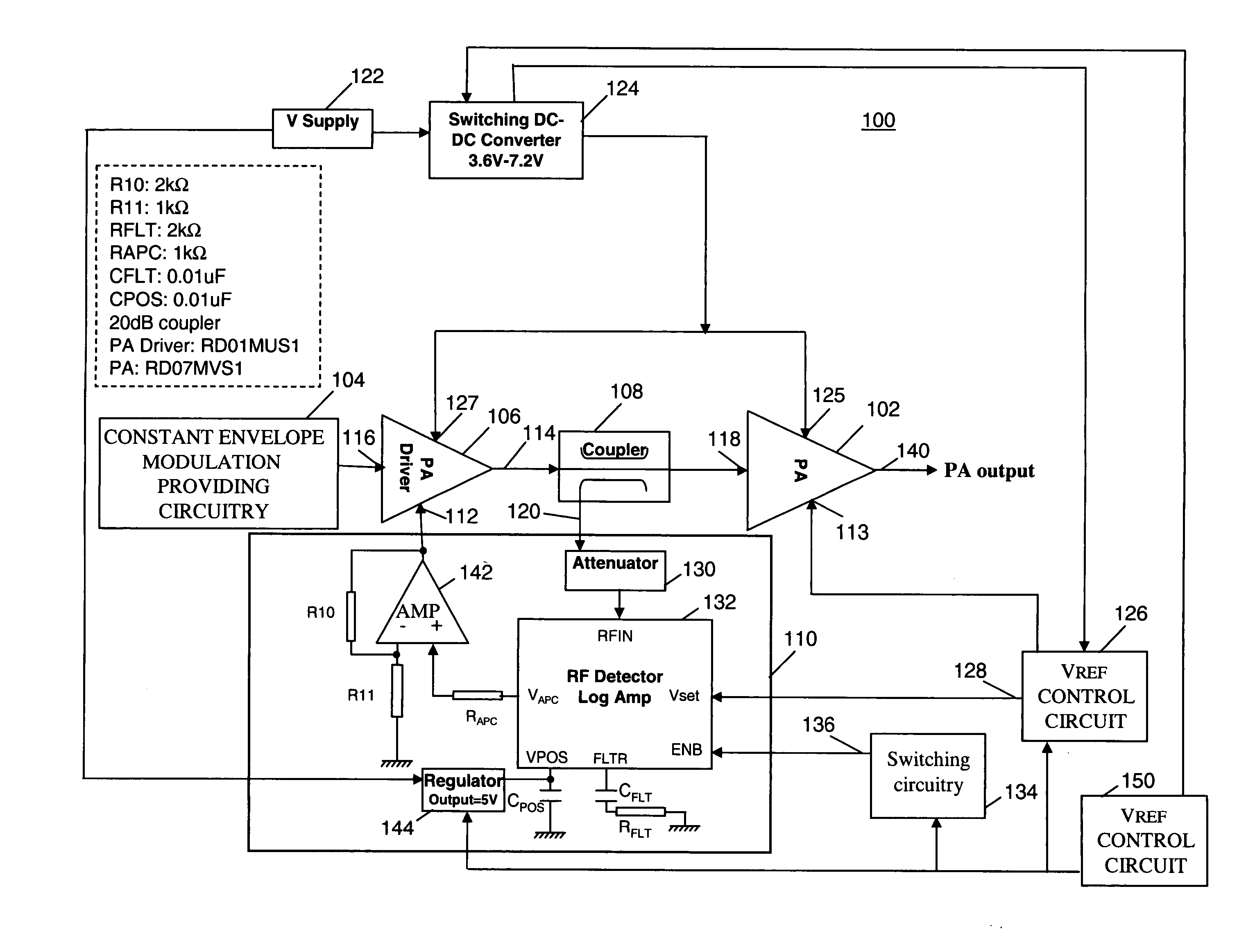
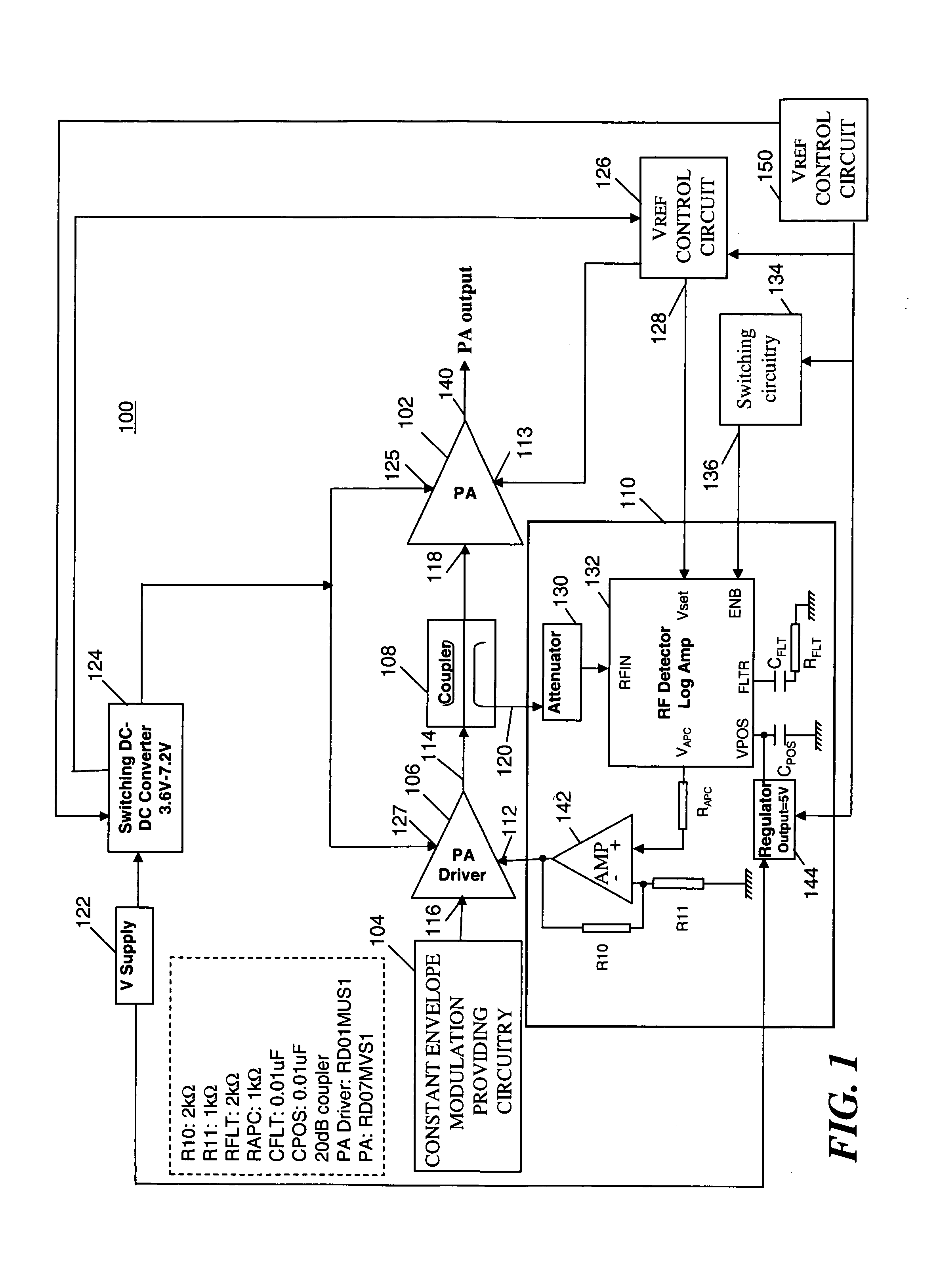
[0012] Before describing in detail embodiments that are in accordance with the present invention, it should be observed that the embodiments reside primarily in combination of method steps and apparatus components relating to a radio frequency power amplifier circuit for a constant envelope modulated signal to substantially maintain the amplified signal at a constant predefined amplitude. Accordingly, the apparatus components and method steps have been represented by conventional symbols in the drawings, showing only those specific details that are pertinent to understand the embodiments of the present invention so as not to obscure the disclosure with details that will be readily apparent to those of ordinary skill in the art having the benefit of the description herein.

[0013] In this document, relational terms such as first and second, top and bottom, and the like may be used solely to distinguish one entity or action from another entity or action without necessarily requiring or...


PUM


Abstract

A method (200) and circuit (100) for substantially maintaining an amplified constant envelope modulation signal at a constant pre-defined amplitude. The circuit (100) comprises a constant envelope modulation providing circuitry (104), a power amplifier (102), a power amplifier driver (106), a coupler (108) and a feedback circuit (110). In operation the sensor (110) has an output (120) that provides a radio frequency output signal proportional to an amplitude of an amplified constant envelope modulated radio frequency signal provided to the amplifier input (118) from the power amplifier driver (106). The feedback circuit (110) provides a gain control voltage a driver gain control input to maintain the constant envelope modulation signal at a constant pre-defined amplitude supplied to the amplifier input (118).

Description

FIELD OF THE INVENTION [0001] The present invention relates generally to a radio frequency power amplifier circuit and method. In particular, the present invention relates to a radio frequency power amplifier circuit for constant envelope modulation and a method of maintaining an amplified constant envelope modulated radio frequency signal at a constant predefined amplitude. BACKGROUND [0002] During operation of a power amplifier circuit comprising a Radio Frequency (RF) power amplifier, it is desirable to achieve relatively high amplifier efficiency across desired power levels (power modes). However, when considering a constant envelope modulated RF signal supplied to such a power amplifier circuit, the signal provided to the power amplifier can vary due to varying operating conditions of the circuit (i.e., temperature and supply voltage). Furthermore, with varying power level requirement from the power amplifier, suitable operating efficiency cannot be readily achieved. For any re...

Claims


Application Information

Patent Timeline
IPC IPC(8): H01Q11/12H04B1/04
CPCH03G3/004H03G3/3042
Inventor ARIDAS, NARENDRA KUMARLEE, JOSHUA KHAI HO
Owner MOTOROLA INC
Why Eureka
Try Eureka