Capping device with quick release mechanism and methods of releasing and re-connecting

a capping device and quick release technology, applied in the field of beverage containers and capping devices, can solve the problems of difficult and cumbersome single user, lock ring with another, etc., and achieve the effect of reducing the amount of spindle manipulation

Inactive Publication Date: 2007-04-19
ADCOR INDS
View PDF8 Cites 9 Cited by
  • Summary
  • Abstract
  • Description
  • Claims
  • Application Information

AI Technical Summary

Benefits of technology

[0006] The present invention provides a capping device for fitting caps onto containers. The device includes a spindle for rotating about an operational axis. A connector is releasably coupled to the spindle. The connector is adapted to engage a capping unit for fitting the caps onto the containers. A quick release mechanism operates between a locked position in which the connector is locked to the spindle and an unlocked position in which the connector is releasable from the spindle. The quick release mechanism includes a lock member rotatable relative to the spindle and the connector. The lock member is manually rotated from the locked position to the unlocked position to release the connector from the spindle without requiring any substantially rotation of the spindle or the connector. As a result, the quick release mechanism reduces the amount of manipulation of the spindle or the connector needed to release the connector and capping unit from the spindle when compared to prior art capping devices. Often the connector and capping unit connected thereto weigh several pounds such that manipulation is difficult, but with the quick release mechanism of the present invention, a single user can release the capping unit from the spindle quickly and easily.

Problems solved by technology

As a result, manipulating the second part with one hand in order to rotate the pins back to the unlocked position, while holding the lock ring with another hand, may be difficult and cumbersome for a single user.

Method used


Image

  • Capping device with quick release mechanism and methods of releasing and re-connecting
  • Capping device with quick release mechanism and methods of releasing and re-connecting
  • Capping device with quick release mechanism and methods of releasing and re-connecting

Examples


Embodiment Construction

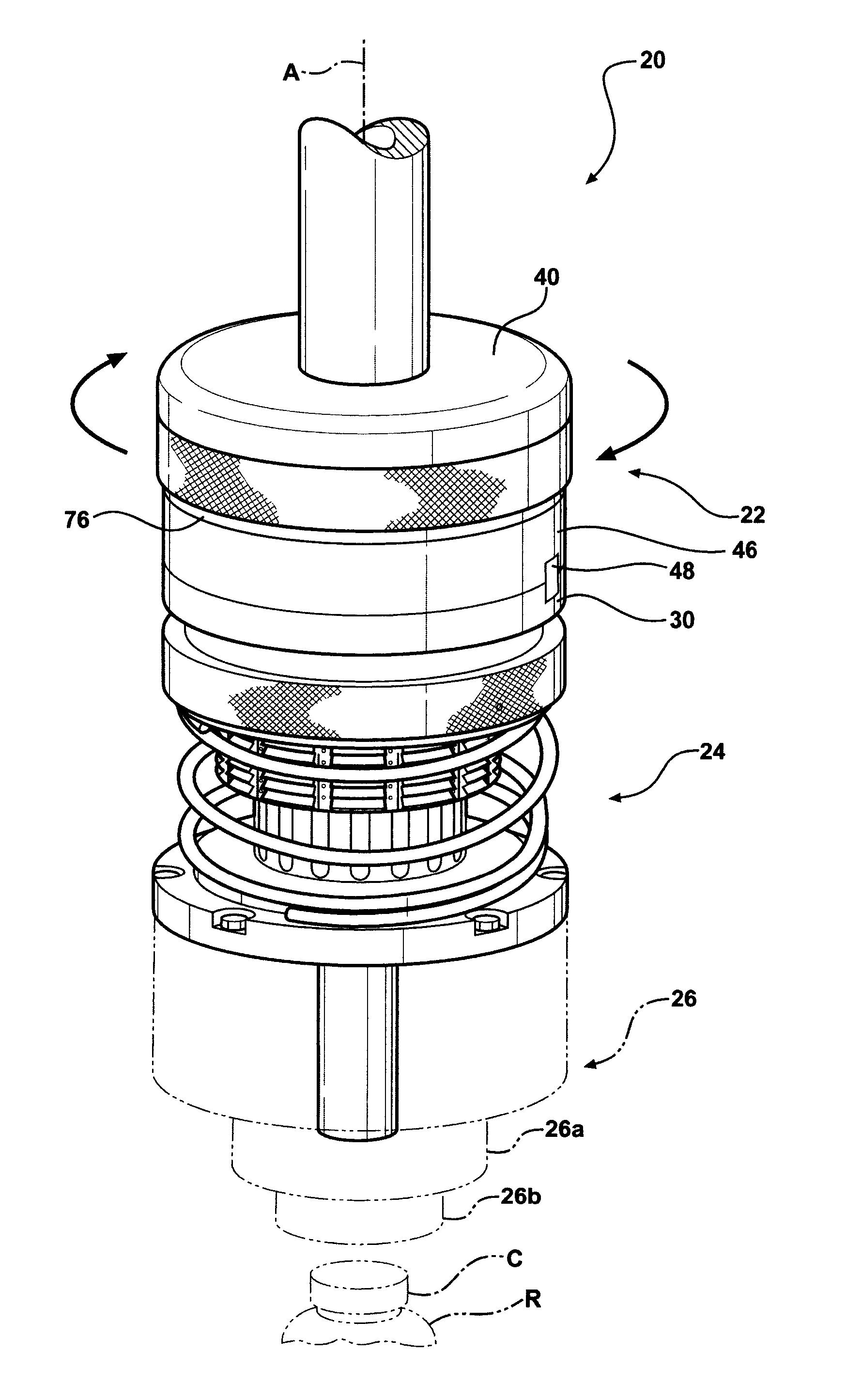
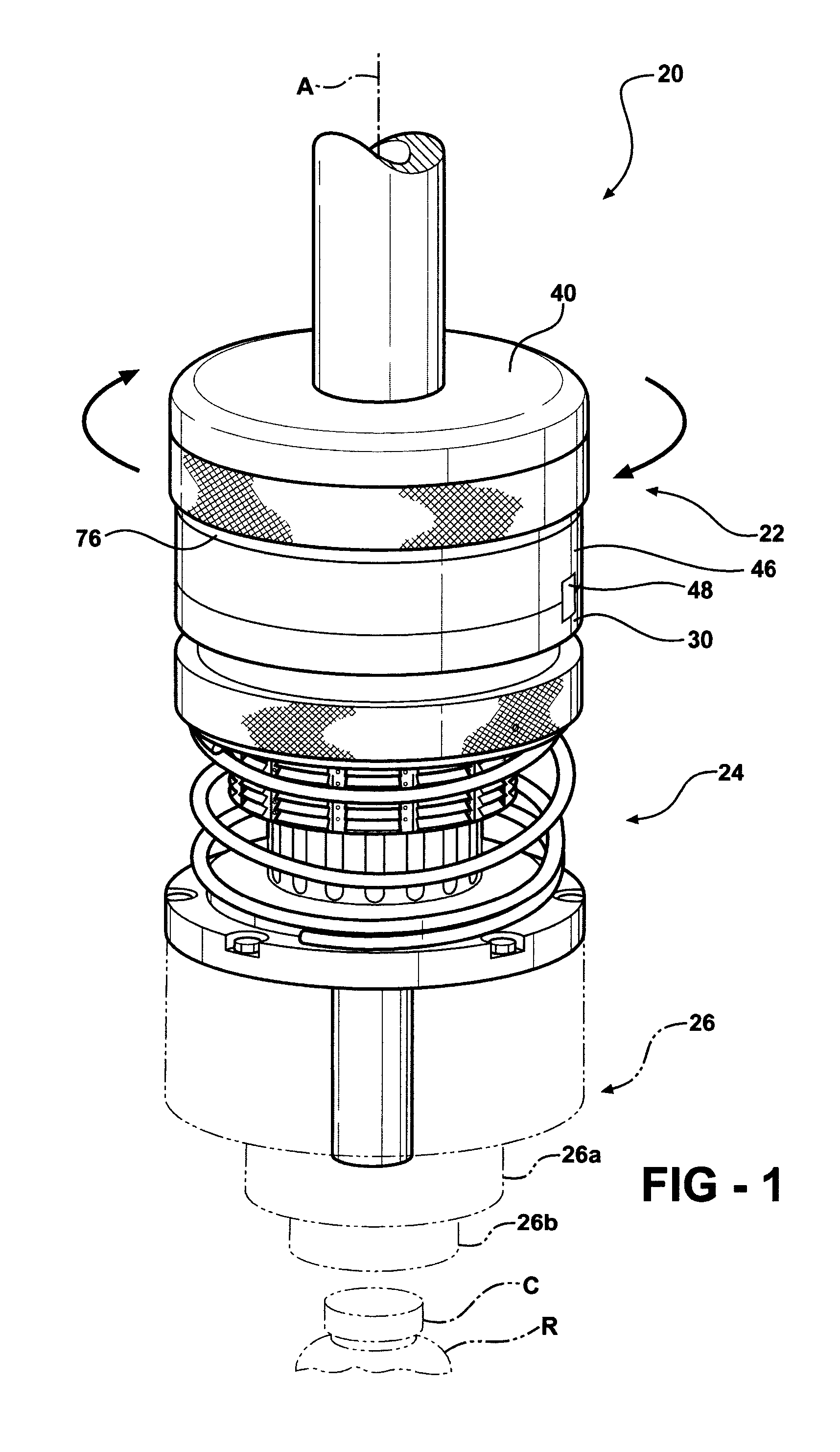
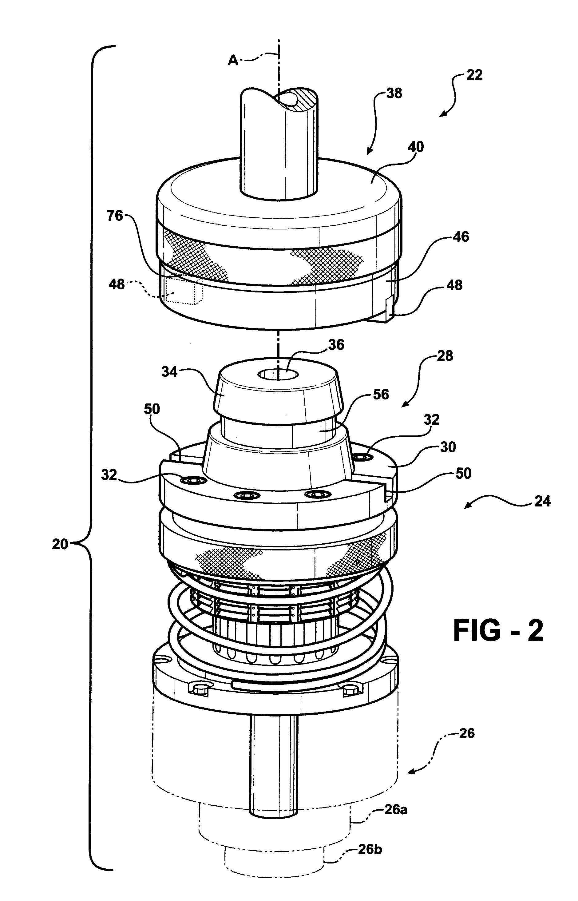
[0027] Referring to the Figures wherein like numerals indicate like or corresponding parts throughout the several views, a capping device is generally shown at 20 in FIGS. 1 and 2. The capping device 20 includes an upper portion 22 and a lower portion 24. As discussed in greater detail below, the upper portion 22 mounts to a capping machine (not shown), which imparts rotation to the capping device 10 about an operational axis A via a drive motor, turret assembly, or other drive source. The lower portion 14 has a capping unit 26 (shown in phantom) mounted at a lower end thereof. The capping unit 26 may comprise a clutch 26a and a cap-engaging portion 26b such as disclosed in U.S. Pat. No. 6,240,678, hereby incorporated by reference. The rotation of the capping device 20 ultimately provides torque to the cap-engaging portion 26b in a conventional manner to thread pre-threaded caps C onto containers R as the containers R and the caps C pass through the capping machine.

[0028] Referring...


PUM

PropertyMeasurementUnit
angleaaaaaaaaaa
rotationaaaaaaaaaa
shapeaaaaaaaaaa

Abstract

A capping device fits caps onto containers by applying an axial force to the caps as they are threaded onto the containers. The capping device utilizes a spindle rotatable about an operational axis for imparting rotation to a capper unit. A connector coupled to the capper unit is releasably coupled to the spindle by a quick release mechanism. The quick release mechanism is normally biased in the locked position and is configured to automatically move from the unlocked position back to the locked position when the connector mates with the spindle as a user re-connects the capping unit back to the spindle. Methods of releasing and re-connecting the capping unit to the spindle are also disclosed.

Description

RELATED APPLICATIONS [0001] This application claims the benefit of U.S. Provisional Patent Application Ser. No. 60 / 723,390, filed on Oct. 4, 2005, the advantages and disclosure of which are hereby incorporated by reference.FIELD OF THE INVENTION [0002] The present invention generally relates to a capping device for fitting caps onto containers, particularly beverage containers. More specifically, the present invention relates to the capping device having a quick release mechanism for quickly and easily connecting and disconnecting a capping unit to and from a spindle of the capping device. BACKGROUND OF THE INVENTION [0003] Capping machines typically utilize multiple capping devices, also known as capping heads or headsets, for fitting pre-threaded caps onto containers to secure contents disposed inside the containers. A typical capping device includes a spindle operatively coupled to a drive source such as a drive motor or turret assembly to impart rotation to the spindle. A cappin...

Claims


Application Information

Patent Timeline
Patent Type & Authority Applications(United States)
IPC IPC(8): B67B3/20
CPCB67B3/2066B67B2201/10Y10T279/17957Y10T29/53322Y10T29/49815
Inventor BROWN, MICHAEL J.
Owner ADCOR INDS
Why Eureka
Try Eureka