Oil separator

a technology of oil separator and oil stream, which is applied in the direction of separation process, machine/engine, mechanical apparatus, etc., can solve the problems of not taking into account the oil-laden air stream, and achieve the effect of minimizing the oil discharge, simple and economical manufacturing, and maximizing the flow cross section

Active Publication Date: 2007-04-19
MANN HUMMEL GMBH
View PDF6 Cites 16 Cited by
  • Summary
  • Abstract
  • Description
  • Claims
  • Application Information

AI Technical Summary

Benefits of technology

[0024] In principle, the openings may be adapted to the functional requirements of the oil separator. These requirements are determined by the function of the housing in which the oil separator is installed. The primary requirement to be mentioned is the volumetric flow rate used to ventilate the housing. In the housing of a thermodynamic retarder, for example, this volumetric flow rate is decisive for the response time of the unit and thus for the braking rate. To vary the ventilation rate of the housing, valves may be used to open additional cross-sectional flows that bypass the defined opening through a bypass opening as needed during the ventilation cycle of the housing. This defined opening for limiting the volumetric flow rate makes it possible to regulate the flow in an advantageous and simple manner without any additional components. It is simple and economical to manufacture and is moreover fully integrated into the oil separator.
[0025] Yet another advantageous embodiment of the invention is obtained particularly with the aforementioned condensate separation space. The condensate separation space preferably receives flow through the center and has outlets or discharge openings on its exterior faces. To prevent the separated oil from going through the discharge openings, the discharge openings are formed in the boundary wall substantially above the lower end face of the condensate separation space. Thus, the lateral boundary faces form a barrier that prevents the separated oil from getting beyond the discharge openings.
[0026] The air outlets of the separation space do not necessarily have to lead directly to the outside but may also be separated from the air outlet by a gap. Preferably, the lower end faces of the separation space are sloped inwardly to allow the separated oil to drip toward the filter medium. This barrier-type enclosure of the condensate separation space advantageously retains the condensed oil and further minimizes the discharge of oil to the outside of the oil separator.
[0027] In accordance with yet another advantageous embodiment of the invention, the air outlet through which the gas reaches the exterior is disposed on the lateral peripheral faces of the oil separator. Ideally, there is a gap between the air outlet and the discharge openings of the condensate separation space, such that the bottom of the gap is preferably sloped toward the air outlet. The air outlet is flush with the lower edge of the gap. This arrangement advantageously prevents any water that may appear on the outside of the oil separator during cleaning or as a result of weather influences from getting into the interior of the oil separator or into the condensate separation space or from penetrating the filter element. Water

Problems solved by technology

This presents the problem of separating the amounts of oil contained in the outflowing air in the form of droplets or slugs to minimize or entirely eliminate oil emissions.
A drawback in this embod

Method used


Image

  • Oil separator
  • Oil separator

Examples


Embodiment Construction

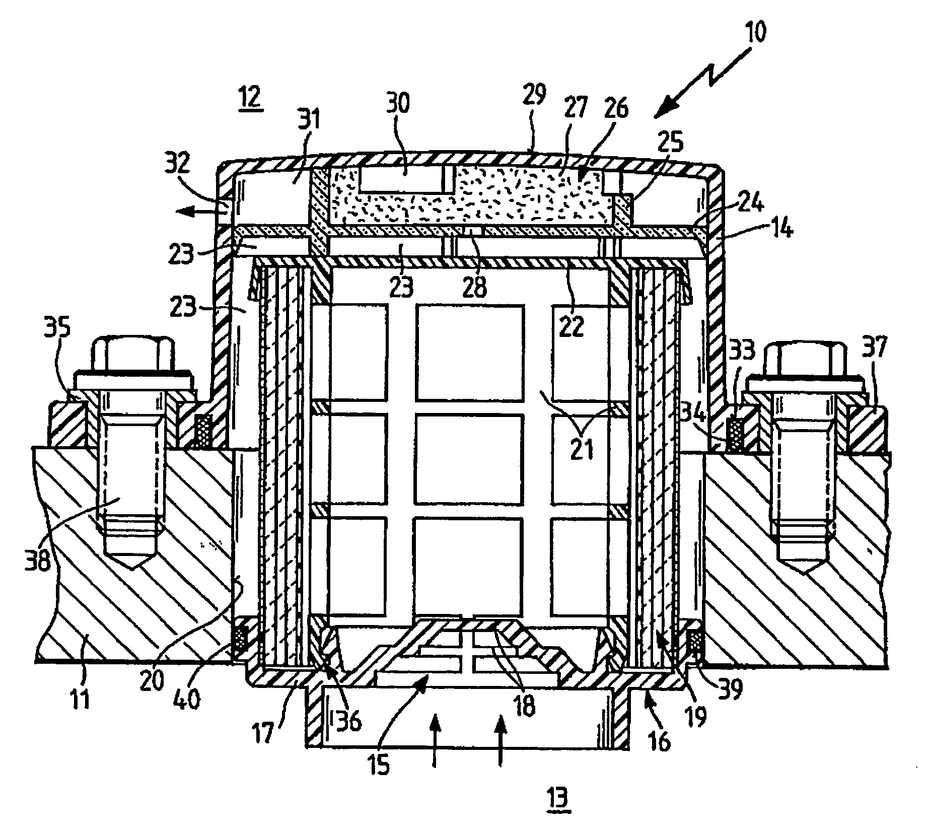
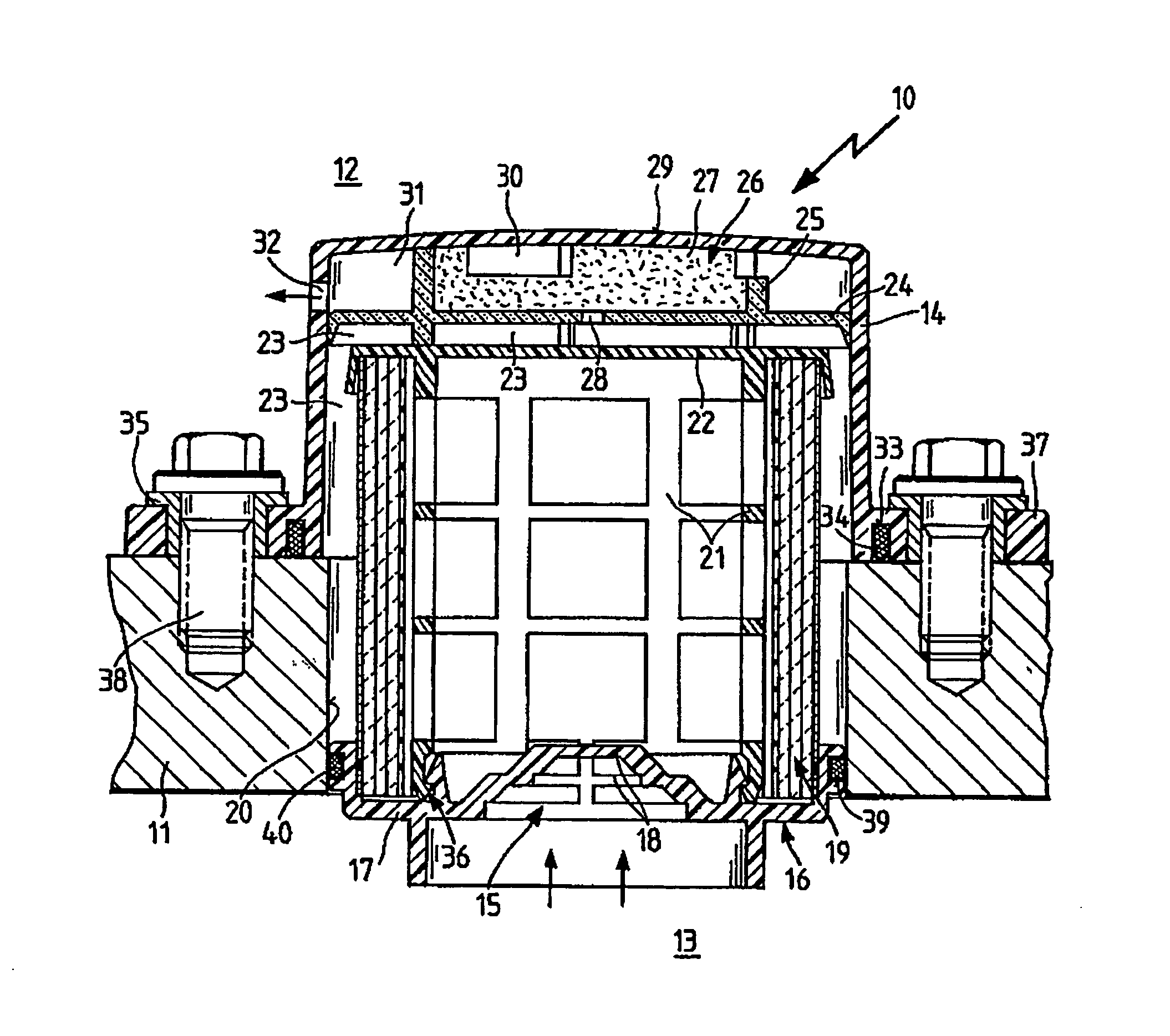
[0032] In the figure, the oil separator 10 is flanged to a housing 11 (only part of which is shown) and secured by screw connections 38. An impingement separator 15, a filter element 19 and a condensate separation space 26 are accommodated within the outer casing 14. The outer casing 14 encloses the oil separator 10 around the periphery and is constructed as an integral unit with an end face of the outer casing 29. As an alternative to this embodiment, the end face of the outer casing 29 may also be constructed as a separate element and fastened to the outer casing 14. In addition, apertured receiving lugs 37 are formed on the outer casing 14, which are tightened to the housing 11 by a screwed connection 38 using metal bushings 35. To terminate the outer casing 14 on the housing 11 so as to form a seal, an elastomer seal 34 is seated in a circumferential groove 33 to produce a tight connection with the housing surface. Thus, the interior of the housing 13 is separated from the exter...


PUM

PropertyMeasurementUnit
Sizeaaaaaaaaaa
Areaaaaaaaaaaa
Metallic bondaaaaaaaaaa

Abstract

An oil separator for separating entrained oil from a gas stream, the separator being arranged on a housing wall which divides a housing interior from a housing exterior. A support tube, which is arranged inside an outer casing and carries a filter element on its outer circumference through which gas can flow radially. The support tube is closed at its upper axial end face and communicates at its lower axial end face with the housing interior. An impingement separator is arranged in the vicinity of the lower axial end face of the support tube. The outer casing is closed at its bottom relative to the housing in a sealed manner.

Description

CROSS REFERENCE TO RELATED APPLICATIONS [0001] This application is a continuation of international patent application no. PCT / EP2005 / 051590, filed Apr. 11, 2005, designating the United States of America and published in German on Oct. 27, 2005 as WO 2005 / 099868, the entire disclosure of which is incorporated herein by reference. Priority is claimed based on Federal Republic of Germany patent application no. DE 10 2004 018 019.9, filed Apr. 14, 2004.BACKGROUND OF THE INVENTION [0002] The present invention relates to an oil separator for separating oil from a gas stream, and to the use of an oil separator according to the invention in a ventilation filter for a thermodynamic retarder. [0003] Oil separators of this type are often mounted on oil tanks or housings in which the oil flows in and out subject to function. This presents the problem of separating the amounts of oil contained in the outflowing air in the form of droplets or slugs to minimize or entirely eliminate oil emissions....

Claims


Application Information

Patent Timeline
IPC IPC(8): B01D50/00B01D45/08B01D46/00B01D46/24
CPCB01D45/08B01D46/0004B01D46/0031B01D46/2414B01D50/002F01M13/04F01M2013/0438B01D50/20
Inventor HEIKAMP, WOLFGANGZUERKER, MARKUSKUEHLBORN, MANFRED
Owner MANN HUMMEL GMBH
Why Eureka
Try Eureka