Sterile container with sterile filter

a sterile container and filter technology, applied in the field of sterile containers, can solve the problems of filter breaking at the bore, having to be replaced, and having to be completely unusable, so as to achieve the effect of a particularly simple design of the sterile container

Inactive Publication Date: 2007-04-19
AESCULAP AG
View PDF15 Cites 11 Cited by
  • Summary
  • Abstract
  • Description
  • Claims
  • Application Information

AI Technical Summary

Benefits of technology

[0007] It is advantageous for the at least one first holding surface and the at least one second holding surface to be arranged so as to face one another. This means that the two holding surfaces would lie directly against one another, were the sterile filter not held clamped between them. As a result, the two holding surfaces may be made very small, so that as large a filter surface as possible remains free. Nevertheless, the sterile filter is held securely.
[0038] A movable mounting between the first holding element and the second holding element can be implemented in a particularly simple way by bearing elements being provided on the second holding element and on the sterile container adjacent to the gas exchange opening for mounting the second holding element movably on the sterile container.

Problems solved by technology

Moreover, in the case of reusable filters, it may happen that the filter starts to tear at the bore when removing the filter for cleaning purposes.
As a result, the filter becomes completely unusable and has to be replaced.

Method used


Image

  • Sterile container with sterile filter
  • Sterile container with sterile filter
  • Sterile container with sterile filter

Examples


Embodiment Construction

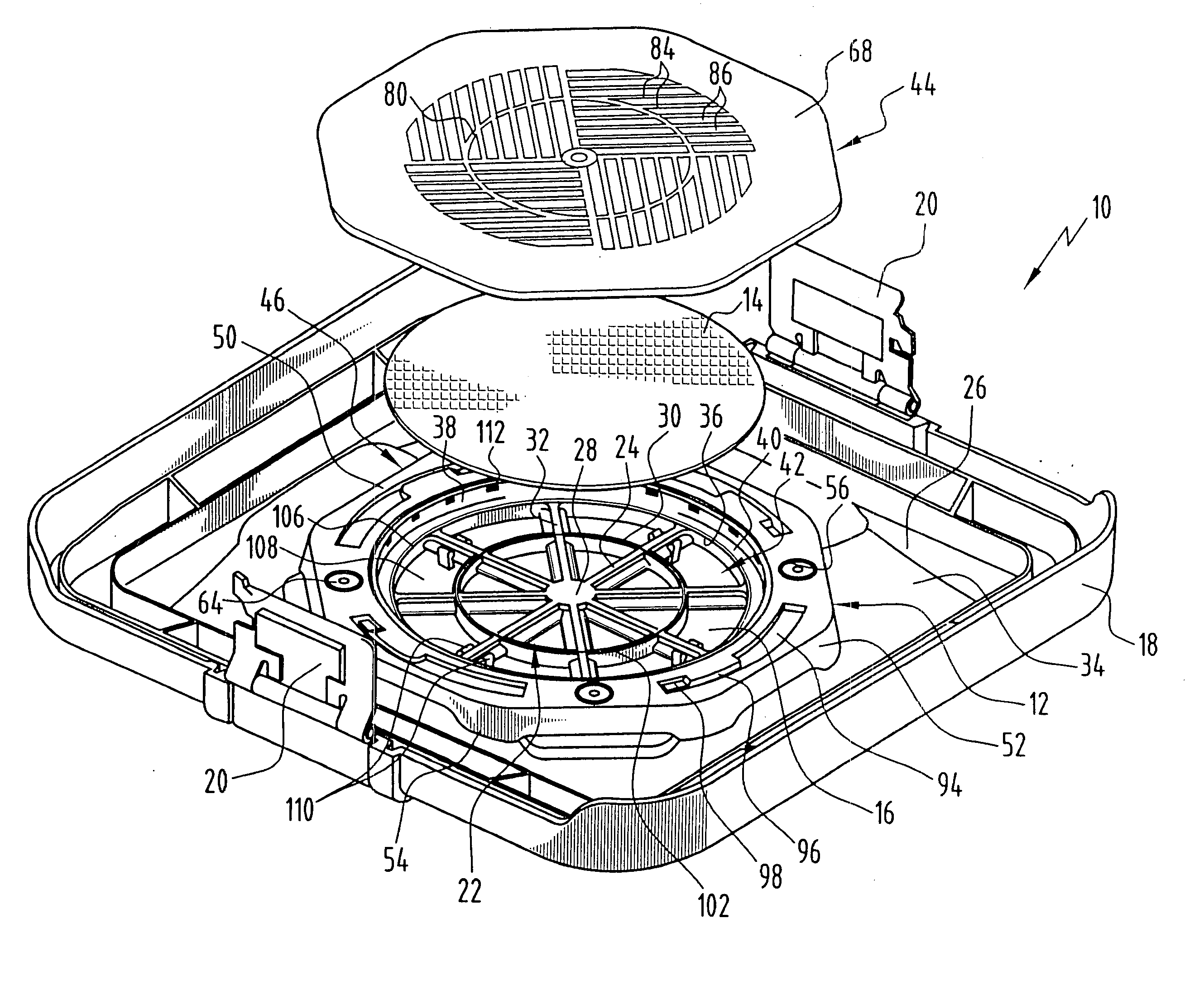
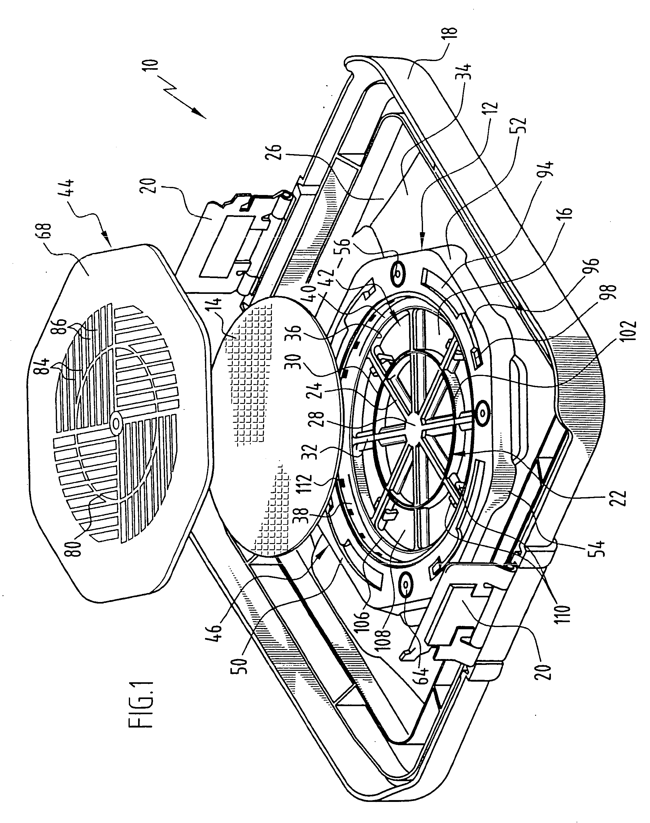
[0052]FIG. 1 shows a lid, generally designated by reference numeral 10, of a sterile container comprising a container tray. A filter holding device, generally designated by reference numeral 12, is arranged on the lid 10. It serves to receive a flat, disc-shaped sterile filter 14, which, in a sterile position, closes a circular opening 16 arranged at the center of the lid 10 in order to, on the one hand, allow gas exchange between an interior enclosed by the container tray and an environment outside of the sterile container, and, on the other hand, to prevent penetration of germs and bacteria into the interior.

[0053] The lid 10 is provided in a conventional manner with a circumferential rim 18, which partially covers side walls of the container tray. Pivotably mounted clamps 20 are provided on the rim 18 of the lid 10 for joining and securing the lid 10 to the container tray.

[0054] The round opening 16 is divided into individual segments by a supporting structure, generally design...


PUM

PropertyMeasurementUnit
cross sectional areaaaaaaaaaaa
pressureaaaaaaaaaa
pressuresaaaaaaaaaa

Abstract

To improve a sterile container, in particular, for receiving and storing surgical instruments or surgical material under sterile conditions, comprising a receiving space formed by a container bottom and container walls, a lid for closing the receiving space, a gas exchange opening for providing a fluid connection between the receiving space and an environment outside of the sterile container, a filter holding device including a first holding element and a second holding element, and a sterile filter, wherein, in a sterile position in which the sterile filter closes the gas exchange opening, the sterile filter is held between the first holding element and the second holding element, so that the design thereof is simplified and damage to the sterile filter is avoided, it is proposed that the sterile filter be constructed so as to have no openings, that the first holding element have at least one first holding surface, that the second holding element have at least one second holding surface, and that in the sterile position the sterile filter be held clamped between the first holding surface and the second holding surface.

Description

[0001] This application is a continuation of international application number PCT / EP2005 / 003939 filed on Apr. 14, 2005. [0002] The present disclosure relates to the subject matter disclosed in international application number PCT / EP2005 / 003939 of Apr. 14, 2005 and German application number 10 2004 020 803.4 of Apr. 16, 2004, which are incorporated herein by reference in their entirety and for all purposes.BACKGROUND OF THE INVENTION [0003] The invention relates to a sterile container, in particular, for receiving and storing surgical instruments or surgical material under sterile conditions, comprising a receiving space formed by a container bottom and container walls, a lid for closing the receiving space, a gas exchange opening for providing a fluid connection between the receiving space and an environment outside of the sterile container, a filter holding device including a first holding element and a second holding element, and a sterile filter, wherein, in a sterile position in...

Claims


Application Information

Patent Timeline
Patent Type & Authority Applications(United States)
IPC IPC(8): B65D6/28A61B19/02A61L2/02A61L2/26
CPCA61B19/026A61B19/0264A61B2019/0213A61B2019/0265A61B2019/0281A61L2/022A61L2/26A61L2202/24A61B50/30A61B50/31A61B2050/006A61B2050/3011A61B2050/311
Inventor JAKAB, MARIANAOERTMANN, FRIEDRICH-WILHELMSCHUSTER, STEFANRENNER, TORSTEN
Owner AESCULAP AG
Why Eureka
Try Eureka