

Inertia-actuated locking device
a locking device and actuation technology, applied in the direction of accident situation locks, constructions, fastening means, etc., can solve the problems of increasing the amount of force that a user must apply, increasing long installation time, so as to reduce the vehicle production cost, facilitate installation, and efficient packaging construction
- Summary
- Abstract
- Description
- Claims
- Application Information
AI Technical Summary
Benefits of technology
Problems solved by technology
Method used
Image

Examples
Embodiment Construction
[0031] In the following figures, the same reference numerals are used to identify the same components in the various views.
[0032] The present invention is particularly suited for an inertia-actuated locking device installed in a latch assembly for a vehicle door. However, various other embodiments are contemplated having different combinations of the described features, having additional features other than those described herein, or even lacking one or more of those features. For instance, it is contemplated that the inertia-actuated locking device can be installed in other suitable latch assemblies as desired.
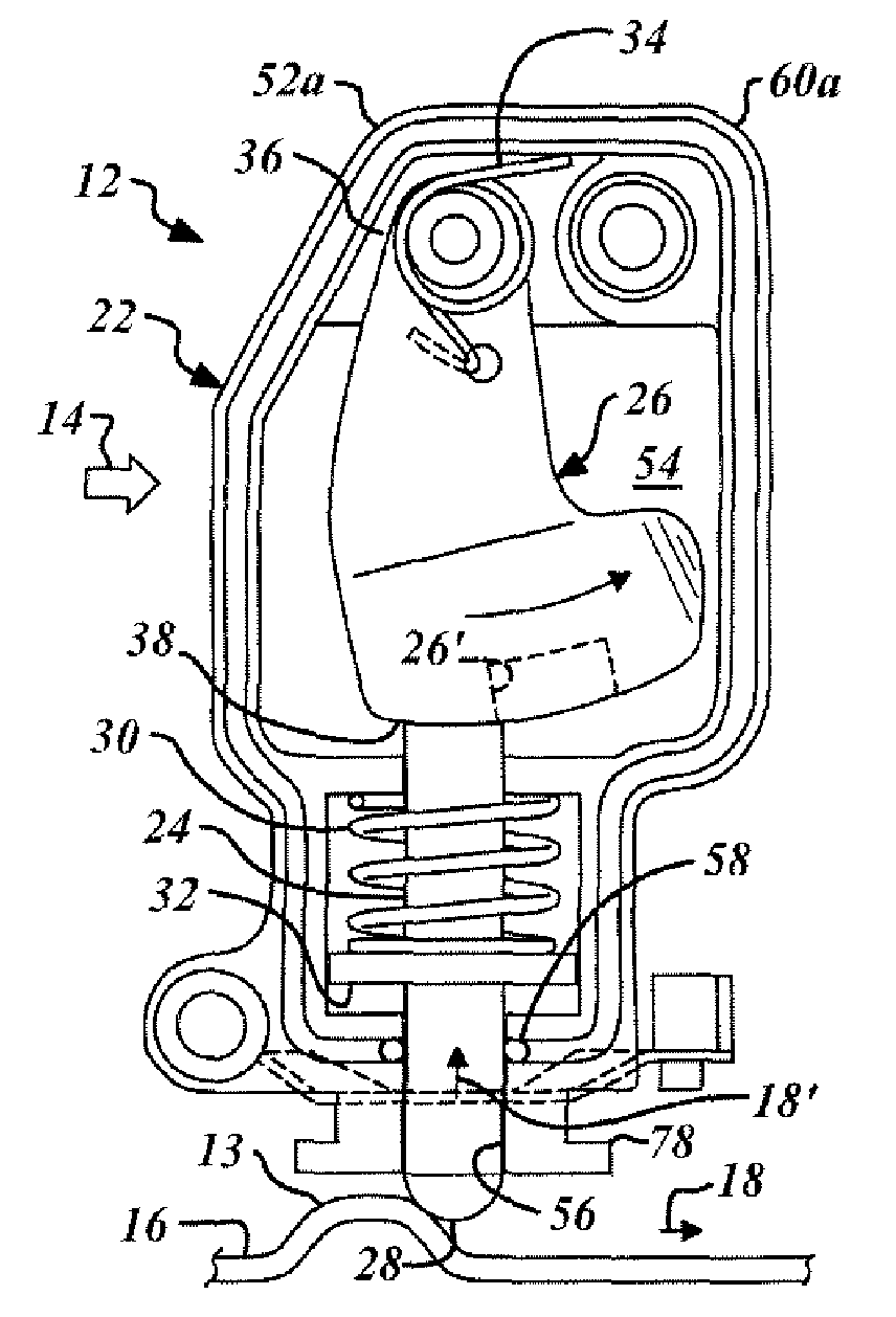
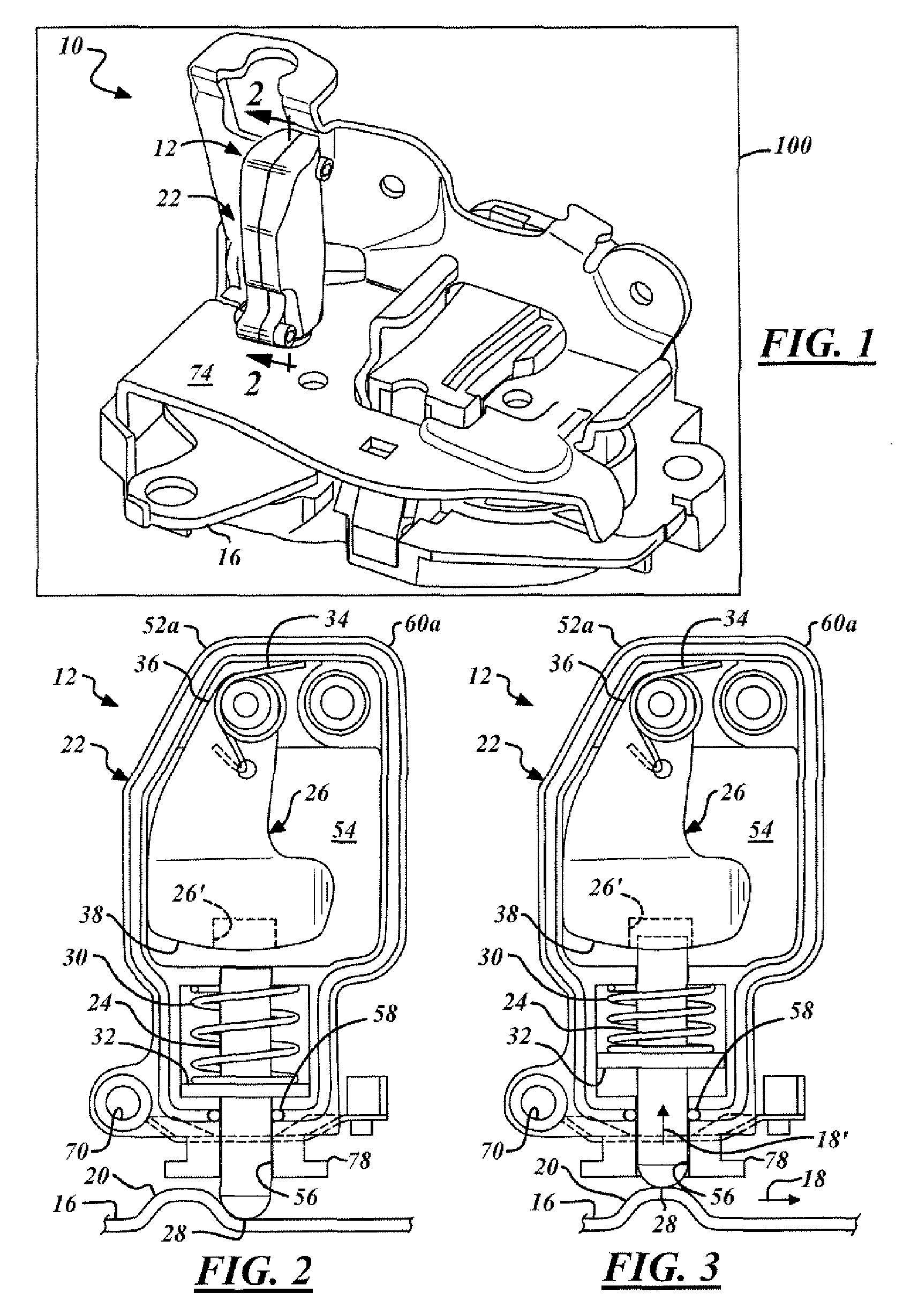
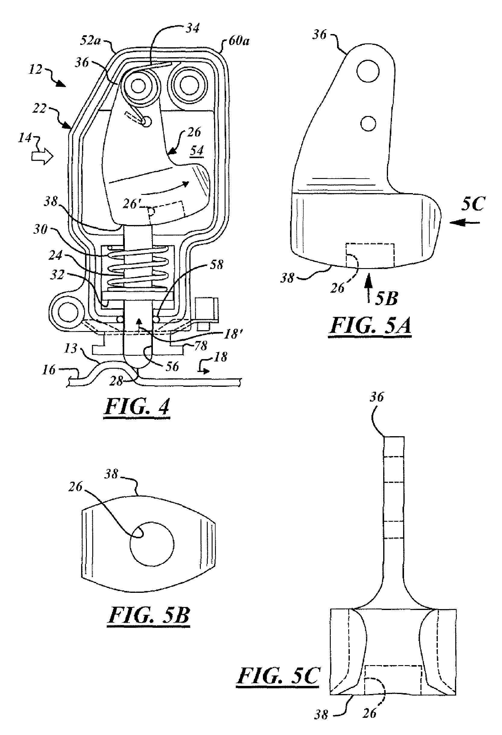
[0033] Referring to FIG. 1, there is shown an improved latch assembly 10 with an inertia-actuated locking device 12 (“locking device”) for a vehicle door, according to one advantageous embodiment of the claimed invention. This locking device 12 is utilized for locking the latch assembly 10 in a latched position under a predetermined inertial force 14 (shown in FIG. 4). In t...
PUM
 Abstract
Description
Claims
Application Information