
Commutation of Brushless Electrodynamic Machines

a brushless electrodynamic machine and electrodynamic technology, applied in the direction of windings, magnetic circuit shapes/forms/construction, salient poles, etc., can solve the problems of a commutator and a set of brushes used in brushed dc electric motors, a relatively complicated external electronic driver (i.e., controller) that controls commutation, and a relatively small number of brushes

Inactive Publication Date: 2007-04-19
REGAL BELOIT AMERICA
View PDF8 Cites 13 Cited by
  • Summary
  • Abstract
  • Description
  • Claims
  • Application Information

AI Technical Summary

Benefits of technology

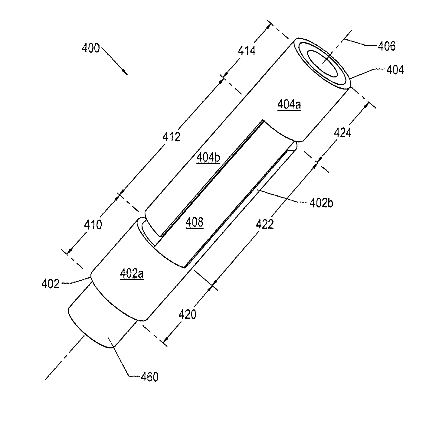
[0009] A method, apparatus and system for selectably directing power signals to coils of active field pole members in brushless electrodynamic machinery are disclosed. In one embodiment, a field pole commutator includes a power transfer region configured to transfer at least a first power signal and second power signal to the coils. It also includes a first power region and a second power region configured to provide the first power signal and the second power signal, respectively, to the power transfer region. The first power region and the second power region eac

Problems solved by technology

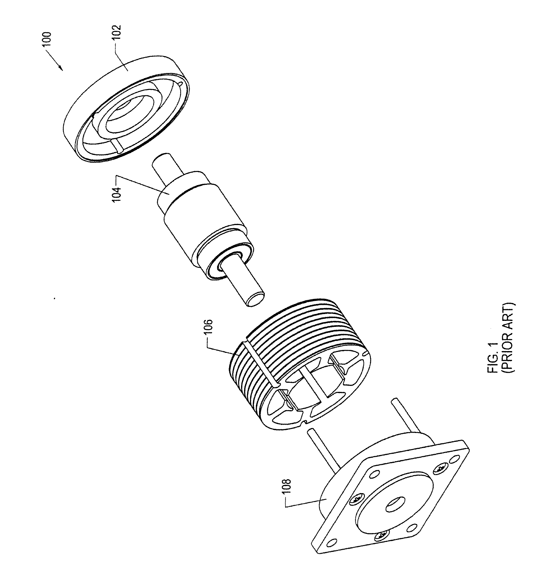
At least one drawback to brushless DC electric motor 100 is that laminated yoke 106 generally forms suboptimal flux paths.
Another drawback is that the external electronic driver (i.e., controller) that controls commutation for brushless DC electric motor 100 is relatively more complicated and thus more expensive to implement than a commutator and a set of brushes used in brushed DC electric motors.
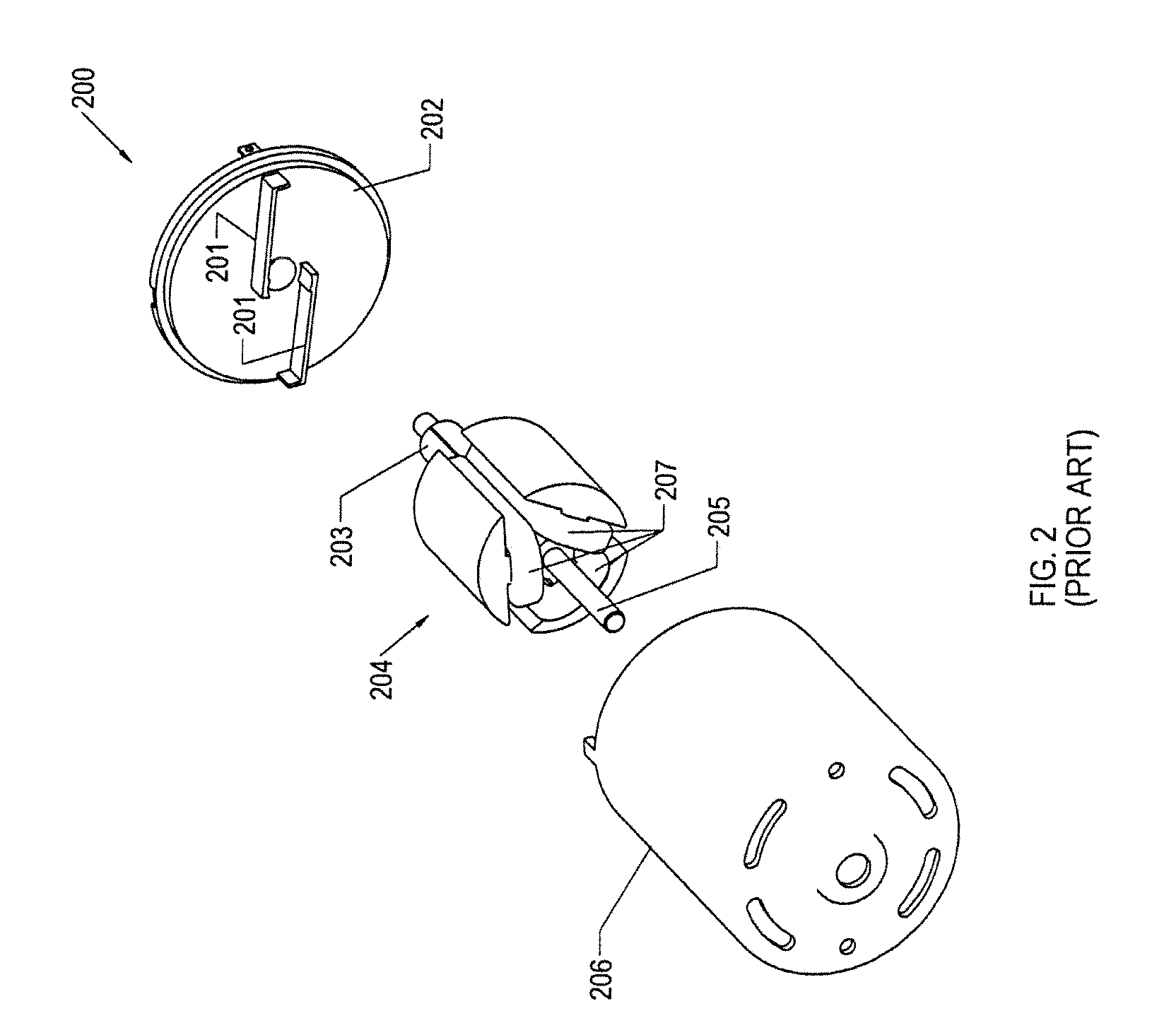
At least one drawback is that thermal energy, or heat, is generated by the one or more coils at a location that is relatively distant from the outside surface of the motor, thereby making it relatively difficult for heat to dissipate from the coils of rotor assembly 204.

Method used


Image

  • Commutation of Brushless Electrodynamic Machines
  • Commutation of Brushless Electrodynamic Machines
  • Commutation of Brushless Electrodynamic Machines

Examples


Embodiment Construction

Definitions

[0026] The following definitions apply to some of the elements described with respect to some embodiments of the invention. These definitions may likewise be expanded upon herein.

[0027] As used herein, the term “air gap” refers to a space, or a gap, between a magnet surface and a confronting pole face. Such a space can be physically described as a volume bounded at least by the areas of the magnet surface and the pole face. An air gap functions to enable relative rotation between a rotor and a stator, and to define a flux interaction region. Although an air gap is typically filled with air, it need not be so limiting.

[0028] As used herein, the term “back-iron” commonly describes a physical structure (as well as the materials giving rise to that physical structure) that is often used to complete an otherwise open magnetic circuit. In particular, back-iron structures are generally used only to transfer magnetic flux from one magnetic circuit element to another, such as e...


PUM


Abstract

A method, apparatus and system for selectably directing power signals to coils of active field pole members in brushless electrodynamic machinery are disclosed. In one embodiment, a field pole commutator includes a power transfer region configured to transfer at least a first power signal and second power signal to the coils. It also includes a first power region and a second power region configured to provide the first power signal and the second power signal, respectively, to the power transfer region. The first power region and the second power region each are configured to rotate together with the power transfer region about an axis of rotation. In one embodiment, the field pole commutator is implemented in a brushless direct current (“DC”) current motor, which includes a rotor having permanent magnets and a plurality of active field pole members. Each active field pole member has one or more coils wound about the periphery of field pole members to form said plurality of active field pole members. In a specific embodiment, permanent magnets of the rotor include either conical magnets or cylindrical magnets, or both.

Description

CROSS REFERENCE TO RELATED APPLICATIONS [0001] This application claims the benefit of U.S. Provisional Application Ser. No. 60 / 724,055, entitled “Commutation of Brushless Electrodynamic Machines,” filed Oct. 5, 2005, the contents of which are hereby incorporated by reference in their entirety. [0002] This application incorporates by reference the following documents in their entirety for all purposes: (1) U.S. Pat. No. 7,061,152, entitled “Rotor-Stator Structure for Electrodynamic Machines”; (2) U.S. Provisional Application No. 60 / 724,053, entitled “Motor Module for Linear and Rotary Motors,” filed on Oct. 5, 2005; and (3) U.S. Provisional Application No. 60 / 724,062, entitled “Integrated Stator-Housing Structure for Constructing Electrodynamic Machines”, filed Oct. 5, 2005;BRIEF DESCRIPTION OF THE INVENTION [0003] This invention relates generally to electrodynamic machines and the like, and more particularly, to a field pole commutator for a rotator-stator structure of a direct curr...

Claims


Application Information

Patent Timeline
IPC IPC(8): H02K21/12H01R39/04H02K13/04
CPCH02K13/006H02K21/12H02K23/62
Inventor PETRO, JOHN PATRICKWASSON, KEN GEORGEMILLER, LAWRENCE EDWARD
Owner REGAL BELOIT AMERICA
Learn More